Torque Wrench Use and Care
Best practices for how to operate and maintain Park Tool torque wrenches and torque drivers.
Introduction
Torque wrenches are simply tools for measuring resistance to rotation. There is a correlation between the tension in the bolt and the effort it takes to turn it. Any tool, even a torque wrench, should be used with common sense. A cross-threaded bolt will not properly tighten even with a torque wrench. The mechanic must be aware of the purpose of torque, and what torque and fastener preload are doing to the component joint. It is also important to consider thread preparation, which is discussed in detail in this article. For a more in-depth look at the concept of torque, see Torque Specifications and Concepts.
In general, torque wrenches should be treated as precision measuring instruments, and should be used and stored with care. Hard impacts, liquids, or exposure to other hazards will negatively affect the accuracy of torque tools.
Park Tool offers three styles of torque tool — best practices for each style is covered below:
Click Type
Park Tool offers two models of “click” style torque wrenches. Both wrenches use 3/8″ square drive to accept standard 3/8″ bits. The TW-5.2 has a range of 2–14 Nm (18–124 inch-pounds). The TW-6.2 has a range of 10–60 Nm (88–530 inch-pounds).
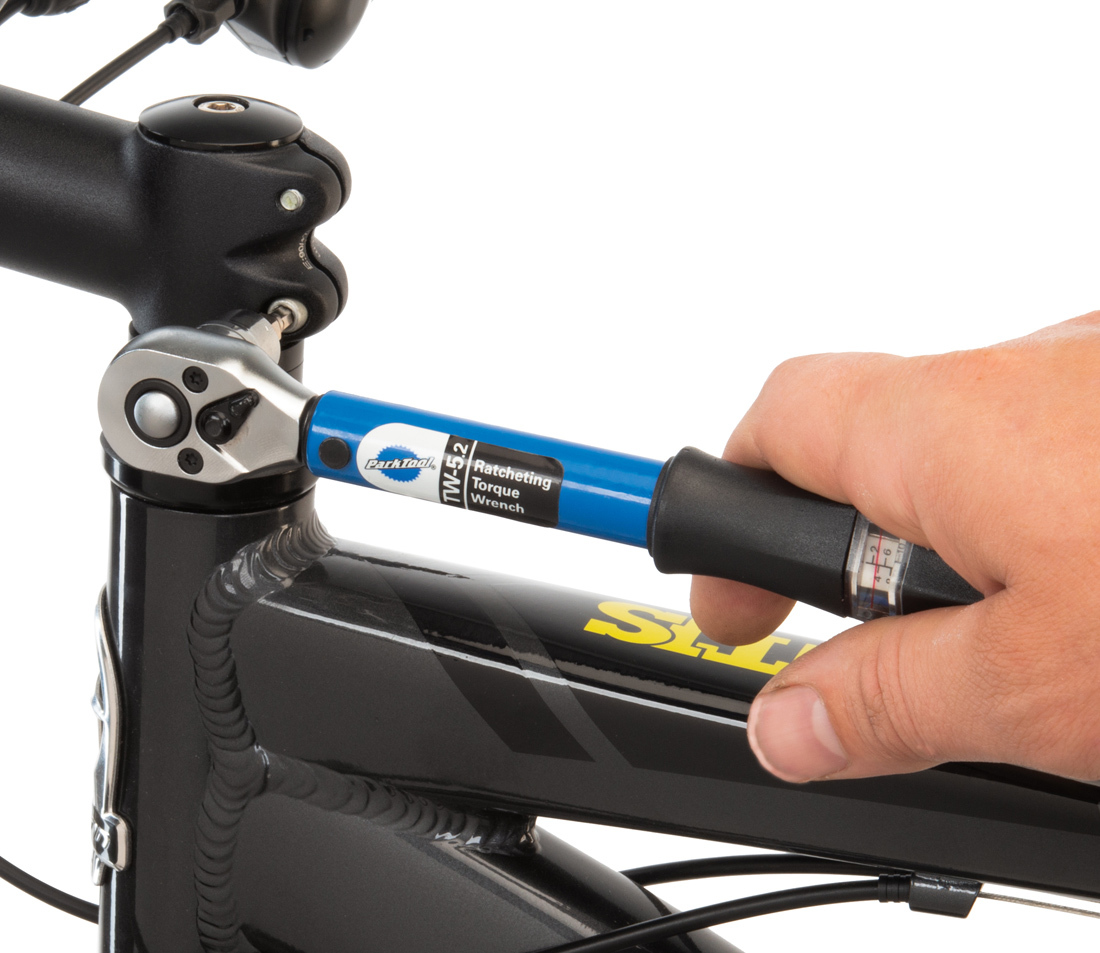
The term “click type” can be misleading. This design of torque wrenches uses a pivoting (or “deflecting”) head. There is a spring that is compressed by turning the handle. At higher torque settings, the spring is compressed more which will allow the head to deflect only at higher resistance, often resulting in an audible “click” noise. But at lower settings, the deflection of the head may create little or no noise. This is because the detent in the wrench has a light action at low torque settings allowing it to be more accurate. This prevents the wrench from slightly exceeding the torque as the tail of the head hits the side of the tube.
The deflection of head — not the “click” noise — indicates that the resistance or torque has been reached. For this reason, use your ears and eyes when using a click-type torque wrench, especially at lower torque settings. Turning a click-type torque wrench past the point of deflection will over-tighten the fastener or component.
Use
- Flip the ratchet lever to the appropriate position — to the right if tightening clockwise, to the left if tightening counterclockwise.
- Determine the recommended torque for the fastener or component in question.
- Push in the locking ring at the base of the handle and turn counterclockwise. Torque setting is determined by adding two numbers: the number directly above the red line in the scale window and the number aligned with the marker on the locking ring. Release the locking ring once the desired setting has been achieved.
- Install the socket or bit onto the torque wrench by pushing the ball detent release button on the back of the wrench and engaging the socket.
- Engage the socket or bit onto the fastener or component. Be sure the socket or bit is fully engaged and oriented squarely.
- With your hand centered on the handle of the wrench, slowly apply force to the handle.
- Keep an eye on the head of the torque wrench — once the head of the wrench deflects, the set torque value has been achieved. This deflection is often accompanied by a click, but may not be — see above.
Care
To avoid fatiguing the spring, click-type torque wrenches should be wound down to the lowest value on the scale (not zero) when not in use.
It is not advisable to use click-type torque wrenches as common ratchet handles to remove fasteners or components. In doing so, you may exceed the maximum torque value of the wrench and stress its internal components, compromising its accuracy.
With time and use, a torque wrench will eventually need calibration. Our recommendation is every 5000 clicks, or at least once a year for wrenches that see frequent use. See Torque Device Calibration & Repair for more information.
Limiter Type
A torque limiter uses a built-in clutch system designed to release when the resistance at the fastener exceeds the resistance of the clutch. Generally, torque limiters are used on lower-torque fasteners such as stems, bars, rotor bolts, cable pinch bolts, etc.
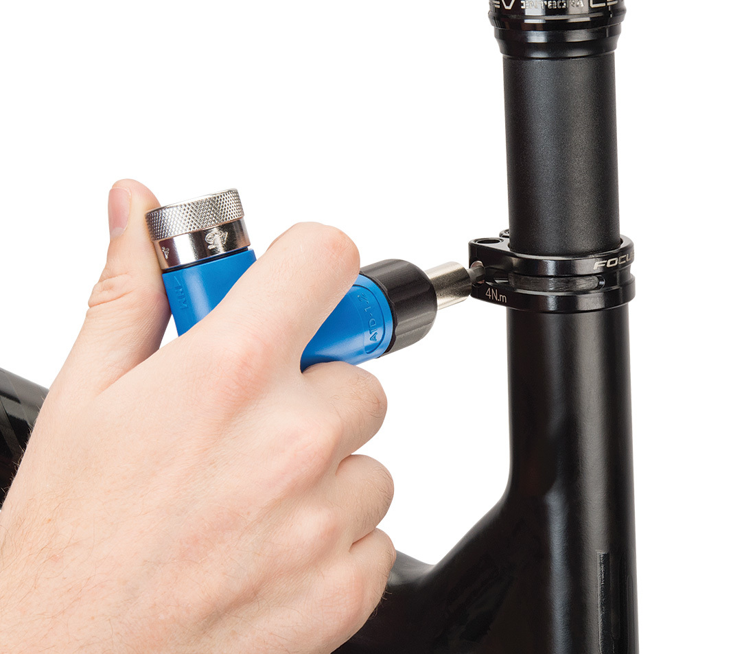
Park Tool offers the ATD-1.2 Adjustable Torque Driver, which covers a range of 4 to 6 Nm. The ATD-1.2 can be used only for setting torque clockwise. When the tool clicks, the torque has been reached. There is no need to continue clicking.
Use
For best results, be sure to turn the tool at a consistent speed. Do not use excessive downforce when turning the driver.
- Determine the recommended torque for the fastener in question.
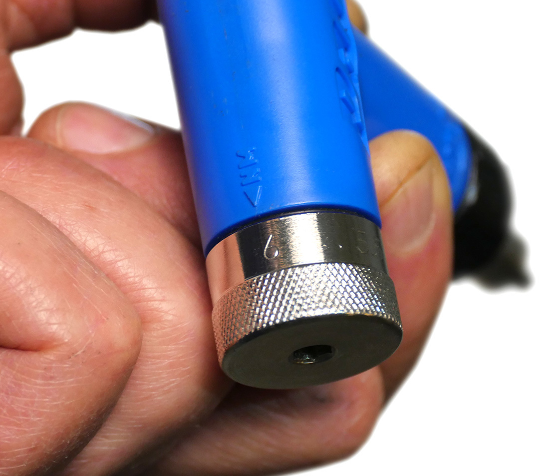
- Adjust the dial of the ATD-1.2 so that the indicator arrow on the tool body is aligned with the desired torque value marked on the dial. The adjustment can be made by hand or using a 5 mm hex wrench.
- Install the appropriate bit into the tool.
- Engage the bit onto the fastener to be torqued. Be sure the bit is fully engaged and oriented squarely.
- Turn the tool until you hear and feel a loud click. The fastener is now torqued.
Care
Once the wrench slips you have reached the set torque. It will not exceed that torque.
It is not necessary to set the ATD-1.2 to any particular setting for storage.
As with click-type torque wrenches, a torque driver will eventually need calibration. Our recommendation is every 5000 clicks, or at least once a year for wrenches that see frequent use. See Torque Device Calibration & Repair for more information.
Beam Type
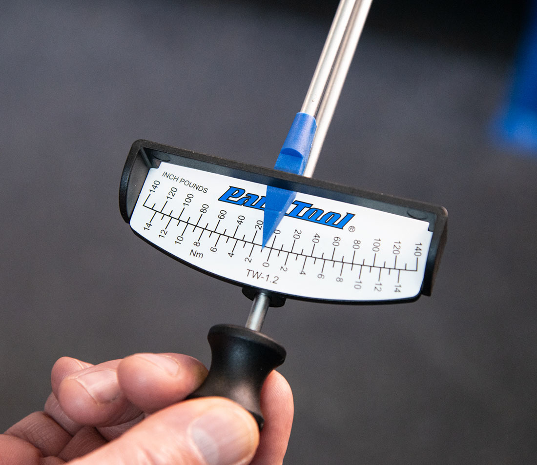
Park Tool offers two styles of beam type torque wrenches. Both wrenches use 3/8″ square drive to accept standard 3/8″ bits. The TW-1.2 has a range of 0–14 Nm (0–140 inch-pounds). The TW-2.2 has a range of 0–60 Nm (0–50 foot-pounds).
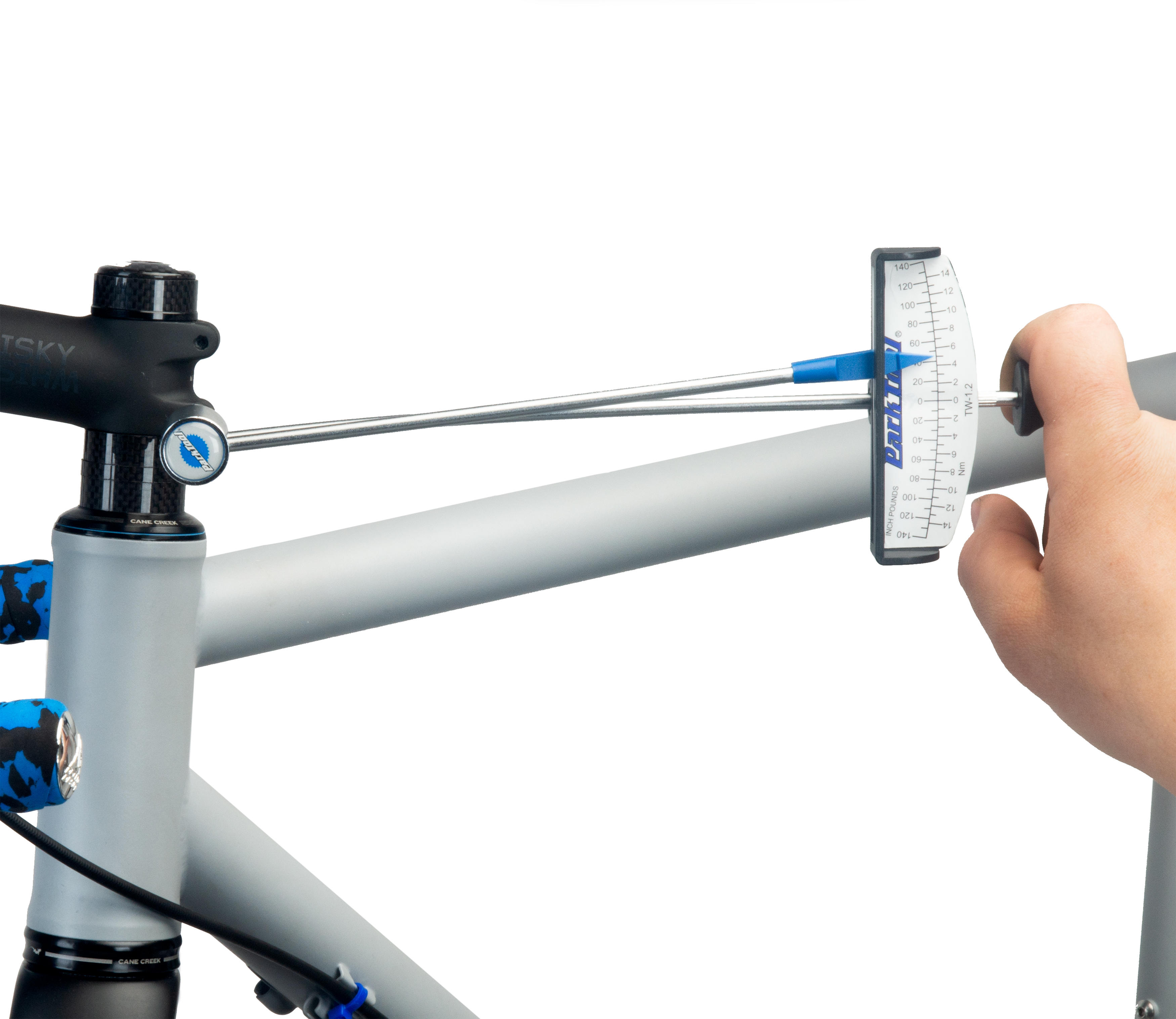
The beam design is relatively simple, and is accurate for both left-hand and right-hand threading. The socket head holds two steel beams, a primary beam and an indicator or pointer beam. The primary beam deflects as the handle is pulled. The separate pointer beam remains un-deflected, and the primary beam below flexes and moves with the handle. The reading is taken at the end of the pointer, at the reading plate on the primary beam. The handle is moved until the desired reading is attained.
Use
When using a beam stye torque wrench, do your best to apply the force at a 90 degree angle to the wrench handle. Try to apply force as close to the center of the handle as possible — hand position can change the wrench’s measurement.
- Determine recommended torque for the fastener or component in question.
- Install the appropriate bit, socket, or other tool (not included) onto the square drive of the wrench. The TW-1.2 and TW-2.2 will accept any tool with a 3/8″ square drive.
- Engage the tool and wrench onto the fastener or tool fitting. Grasp the handle of the torque wrench and apply steady pressure — centered in the middle of the handle — in the direction that tightens the thread.
- While applying pressure, watch the position of the pointer tip on the reading plate. Stop tightening when the pointer tip reaches the desired torque value on the scale plate.
Calibration
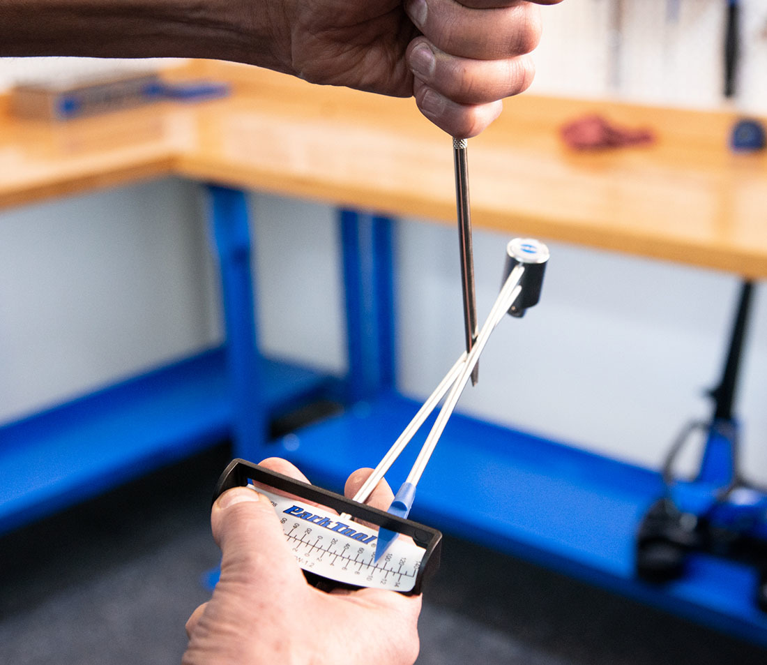
To check tool calibration, inspect the pointer when the tool is at rest. If it is pointing at 0, the tool is calibrated. If it is off zero, bend the pointer shaft unit it points at 0. Place a screwdriver or similar lever between the two beams closer to the head than the scale. Bend the small shaft until the point is at zero when the tool is at rest.
Related articles
Torque Specifications and Concepts View Article