Basic Thread Concepts
This article will discuss the basics of threaded fasteners and fastener tightening. The use of chemical threadlockers will also be discussed. Understanding basic concepts regarding fasteners and threads will improve the skill and knowledge of any mechanic.
Intro to Threads
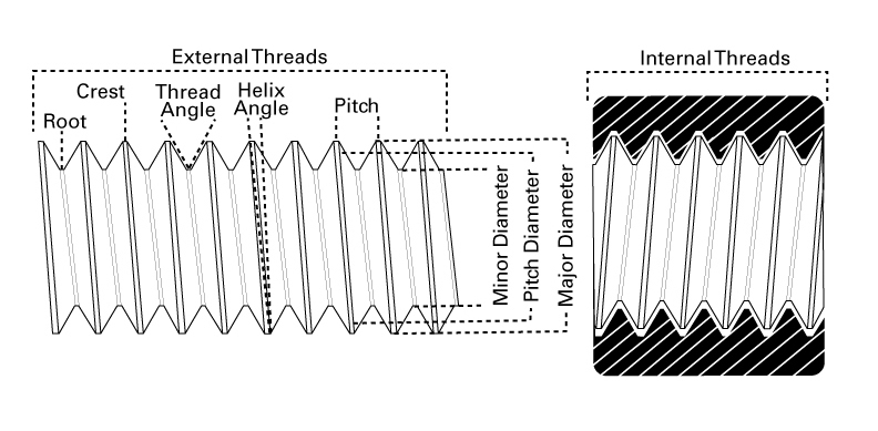
To effectively service fasteners and threaded components, it is important to have a working knowledge of threads. A thread is a continuous helical ridge formed on the inside (nut) or outside (screw) of a cylinder. This ridge is called the crest. Between each crest is a space, called the root. Threads are set at an angle to the axis of the bolt or nut. This slope is called the helix angle. The angle must be sloped, either upward to the right (for right-hand threaded screws) or upward to the left (for left-hand threaded screws). The thread forms a “V” shape between crests. The angle of this “V” is called the thread angle, and is determined by fastener engineers. Most screw threads used on a bicycle use a 60-degree thread angle.
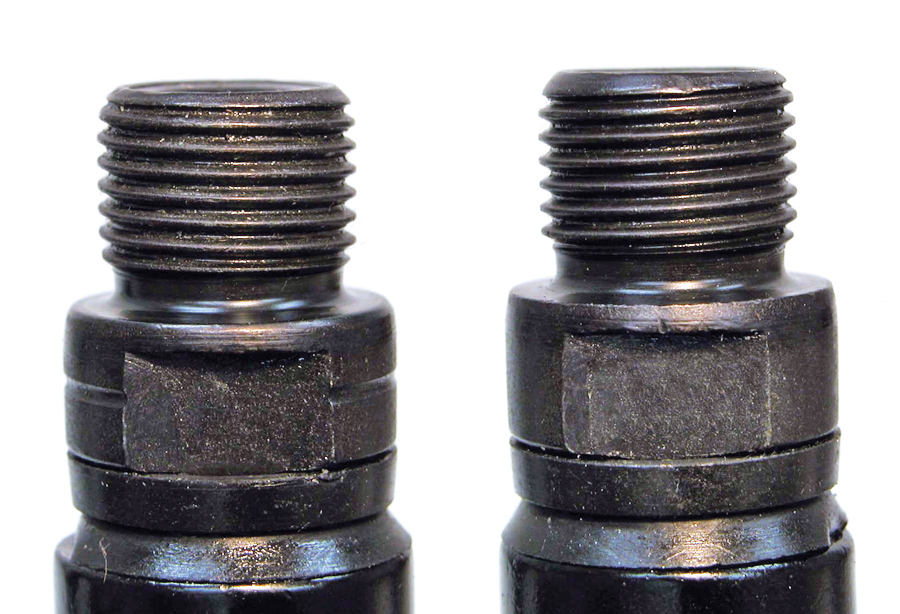
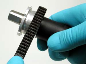
For external threads (bolts), a right-hand thread slopes up to the right, but the internal right-hand thread slopes up to the left. For external left-hand threads, the threads slope up to the left, while the internal left-hand threads slope up to the right. The right-hand screw tightens clockwise (to the right). The left-hand screw tightens counter-clockwise (to the left). Left-hand threads on bicycles are seen on the drive side of bottom bracket and the left pedal. Notice the slope of the threads in the pedals threads below.
Threads are designated or named by two qualities: the external thread major diameter and the pitch measurement.
The major diameter is the outer diameter at the top of the thread crests. In Metric sizing, it is typical to to use the letter “M” before the bolt size, such as “M6” for a bolt with a 6 mm major diameter. Thread sizes are given in nominal sizes, so the exact measurement is generally slightly smaller than the specified size. For example, an M6 bolt may measure 5.8 mm or 5.9 mm, but it is called an M6 bolt. Note: The wrench size for the head of the bolt or nut is not used to determine the size of the thread. For example, the common M6 x 1.0 socket head cap screw uses a 5 mm hex wrench, yet the thread is not called M5.
Thread pitch is the distance from the crest of one thread to another crest measured along the length of the thread. Pitch is best measured using a thread pitch gauge.
So-called “English”/“Standard”/“Imperial”/“SAE” threads are designated by the frequency of how many threads are counted along one inch. This is called “Threads per Inch”, and is abbreviated as TPI. Metric threading uses the direct pitch measurement in millimeters from thread crest to the adjacent thread crest measured along the thread axis. An example of an SAE thread is 9/16″ x 20 TPI (pedal threads). An example of metric thread would be M10 x 1.0 (common rear derailleur bolt). NOTE: The term “Standard” threading is used primarily in the USA. The assumption in the USA is that the common SAE threading is the “standard.”
Typically, if a thread has a pitch designated as TPI, it is a SAE thread and the diameter is given in fractional inch sizes. If the pitch matches the metric standards, the diameter is given in millimeters. However, some thread standards will mix tpi with a metric diameter. Some Italian manufacturers use threads with a metric diameter and SAE thread pitches. For example, the “Italian” bottom bracket thread standard is 36 mm x 24 tpi, and some Italian-made rear axles are 10 mm x 26 tpi.
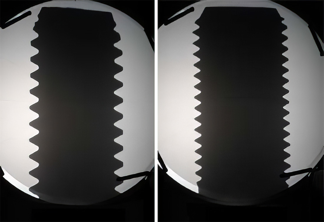
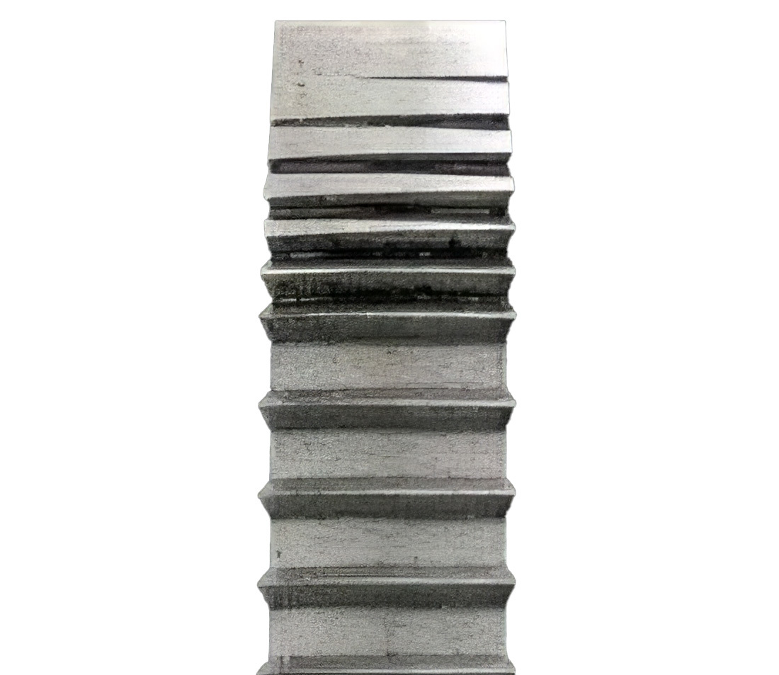
Threads are sometimes identified as “fine” or “coarse.” A fine thread will have a relatively small pitch measurement, and the threads will be closer together. A coarse thread has a relatively larger pitch measurement, and the threads will be further apart. Fine pitch threads are sometimes used to make adjustments. Derailleur adjusting screws are commonly a 0.75 mm pitch. A quarter of a turn on a derailleur screw advances the screw end only 0.19 mm. A fine thread will have less depth as compared to a coarse thread, and consequently are easier to strip. A coarse thread is more resistant to stripping but also less efficient in transmitting torque (turning) into thread tension. Generally, a fine pitch is easier to tighten in that tension is achieved at lower torques. In the image below, two bolts of the same diameter are magnified using an optical comparator. Notice the relatively coarser threads are deeper as compared to the fine threads.
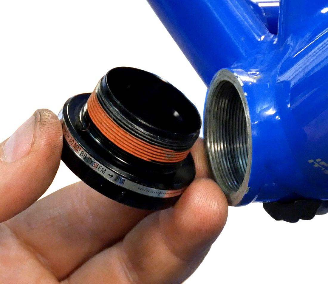
For threads to interchange and match, both the diameter and pitch must match. Another critical aspect of thread fit and interchangeability is call pitch diameter. The pitch diameter is the diameter of the thread at a point where the width across the thread and the width across the groove between threads, are equal. Pitch diameter is difficult to measure directly without special instruments such as the optical comparator. For example, you may have one bottom bracket that seems to fit a bike shell easily. However, a replacement bottom bracket of a different brand may fit the same bike tightly. It is likely the two bottom brackets vary in pitch diameter.
Even when threads are properly sized, there will be play or slop between external and internal threads when engaged. This play is normal and disappears when the fastener is tightened. The thread can be a bit larger or smaller than ideal, and yet the part will still function adequately. However, if tolerances are exceeded, the part may require excessive force to install, or the fit may be quite sloppy, and the thread may fail during tightening.
Bolts and screws are made in different grades of strengths. There is a rating system that is used to mark and identify most industrial bolts. However, the bicycle industry typically uses proprietary bolts without any markings. The SAE (Society of Automotive Engineers) system rates bolts from grade 1 through grade 8. The tensile strength increases with the number. Metric bolts come with a “property class,” a two number system separated by a decimal point.
Thread Formation and Repair
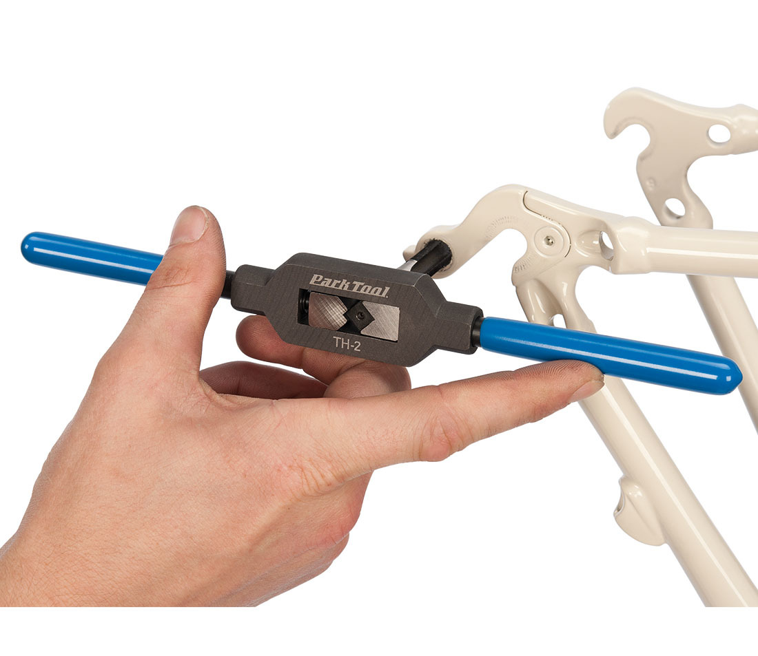
Tapping a derailleur hanger using a TAP-10 and TH-2
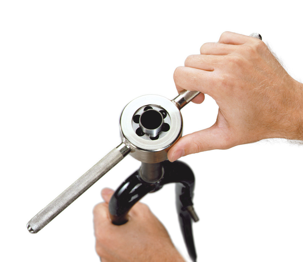
Tapping a fork using an FTS-1
Taps and dies can cut threads. Taps cut an internal thread, such as a bottom bracket shell in the frame. Dies cut an external thread, such as a steering column. Thread may also be cut using a lathe, or they may be rolled, such as threads on a spoke end, or on hub axles. For example, a common spoke diameter is 2 mm in diameter. However, the spoke threading is larger (2.2 mm) than the 2.0 mm shaft. This is because the crest was displaced upwards when the threads were rolled.
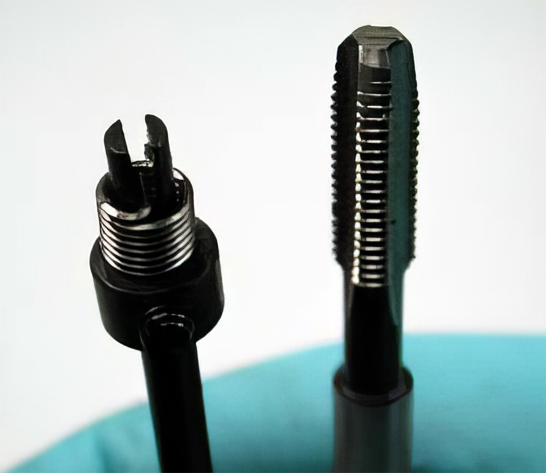
When a thread becomes damaged, there are sometimes options for repair. Typically, when an internal thread becomes damaged, it is damaged at end of the threads, not the middle. If only minor damage has occurred, it may be possible to re-tap the thread. This assumes that enough undamaged thread is remaining to allow proper tightness. As a practical test, after tapping the thread, slightly over-torque from the recommended specification. If the thread is weakened, it will strip and not pass this test. If it does not strip, the thread is adequate, and should survive the use.
Internal threads may sometimes be repaired using a coil system. Companies such as Recoil® and Helicoil® offer repair kits consisting of a tap, coil inserts, and coil driver. The damaged thread is drilled out to a specific size. New larger threads are installed with a specifically sized tap. The inserted coil has the outside diameter of the tap, but the coil inside diameter matches the original thread.
Taps and dies are cut to match the desired thread, and also have a helix angle. This is more difficult to see because the threads are not continuous around the tap or die. In a die, the cutting area is referred to as the “lands.” The lands are separated by “flutes,” the gap between the lands. Larger tap sizes are generally made as “skip toothed” taps, with every other thread missing. This helps prevent build up of cut material in the tap.
It is sometimes possible to tap a damaged internal thread to a larger size, and then use the corresponding bolt or screw. This repair may not work if there is little extra material around the damaged threads. If the internal thread is a bottom bracket, the next larger thread is often the “Italian” threading of 36 mm. This repair is sometimes possible, but the bottom bracket should have all threads removed before tapping. The original thread inside diameter is approximately 34 mm. The bottom bracket shell inside diameter should be 35 mm to correctly cut 36 mm threads. Generally, tapping a bottom bracket to the larger 36 mm x 24 TPI standard is a very difficult slow process. It is also very hard on the taps.
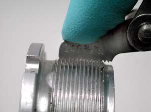
Another option for some external thread repair is a thread file. These are available in both SAE (“English”) and metric thread pitches. This tool acts as a “straight die,” and will trim metal from flattened threads. Hold the die parallel to the helix angle and push the file across the damaged threads.
Tap Drill Size
When cutting new threads in a blank hole, the hole size must be appropriate for the tap. This is size is called the Tap Drill Size. The tap cuts and removes a certain amount of metal, leaving the internal thread. If the hole is too small, the tap will have difficulty removing material, and a great deal of force in turning the tap will be required. The tap will bind in the hole and begin to gall and pull up material, leaving a poor internal thread. If the hole is too large, the tap will cut with little problem, but the internal thread will not be the correct size for the bolt/screw, and failure during tightening or use is very likely.
Manuals on machining contain tables and charts to determine the correct tap drill size. If no chart is available, a simple formula for both SAE (fractional) and metric threads can be used.
Tap Drill Size = Nominal size of tap - pitch
As an example, a hole is required for a 1/4″ x 20 threads per inch. There is a simple conversion for thread per inch into pitch. The pitch (distance from crest to crest) is the inverse of the threads per inch. For 20 threads per inch, 1/20 is equal to 0.05-inch pitch. The correct size hole in this example would be
0.25 -.05 = 0.20-inch, or a 13/64-inch drill bit.
Notice that the coarser the thread, greater the difference between tap drill size and tap size. Finer threads would have less of a difference between the tap and hole size. The thread of 1/4 inch x 28 TPI would require a 0.214 inch tap drill size. In another example, the tap drill size for a 9/16-inch x 20 tpi thread would be: 0.5625 - 0.05 = 0.5125 inch. In a fractional size, this is nominally 33/64 inch.
Using a metric example, a hole is required for an M5 x 0.8 thread. The correct size hole would be 5 mm - 0.8 mm = 4.2 mm, which is approximately 5/32 inch.
Thread Preparation
There is resistance to turning a fastener as it gets tighter. Some resistance comes from friction and rubbing between the internal and external thread surfaces. Because of this, it is common to prepare the threads with lubrication. This can take for form of liquid lubrication, grease, or an anti-seize compound. Even liquid threadlockers provide some lubrication during tightening. As a simple rule of thumb, if the thread size is small, such as a derailleur pinch bolt, a liquid lubricant is adequate. If the thread is large or the torque relatively high, such as a pedal thread or bottom bracket, use a grease or anti-seize compound. There are situations, however, where a manufacturer may recommend no lubrication on the fastener. It is useful to lubricate the threads and under the head of the bolt, especially when the bolt head is turned during tightening.
More information on thread preparation can be found in The Park Tool Guide to Bicycle Lubricants and Compounds.
Threadlockers are special adhesives used in many industries and in many applications. These are available through Park Tool. The commonly available threadlockers are called “anaerobic.” These liquids cure independent of air, and will harden and expand. This hardening and expansion is what gives these materials their special feature. However, threadlockers should not be used to replace proper torque and pre-load when clamping load is important.
Cycling component manufacturers sometimes use an “aerobic,” or “dry” threadlocker for their products, such as on brake caliper bolts. This compound acts primarily as thread filler. If the part is removed, the compound tends to break down, so use a liquid threadlocker to supplement.
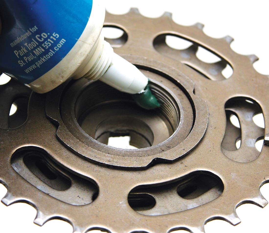
Bottom bracket cup with dry threadlocker preinstalled
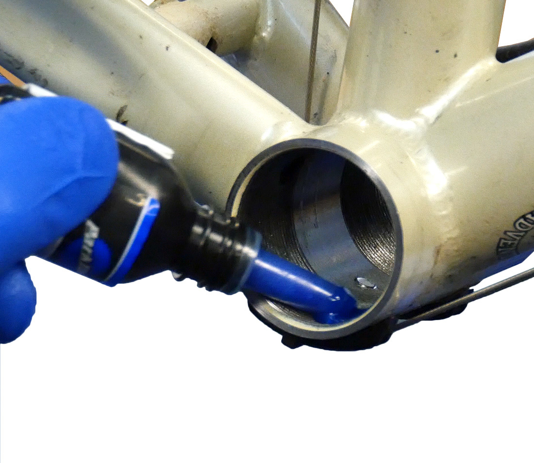
Applying TLR-1 Threadlocker to the threads of a bottom bracket shell
Threadlockers come in different grades of strength. The lighter duty lockers are considered “service removable,” and can typically be removed with normal service procedures. There are compounds that are stronger and extra procedures are often necessary when disassembling, such as heating with a heat air-gun.
Most thread-locking compounds are designed for metals. They are usually not intended for use with plastic, and may both harden and weaken the plastic.
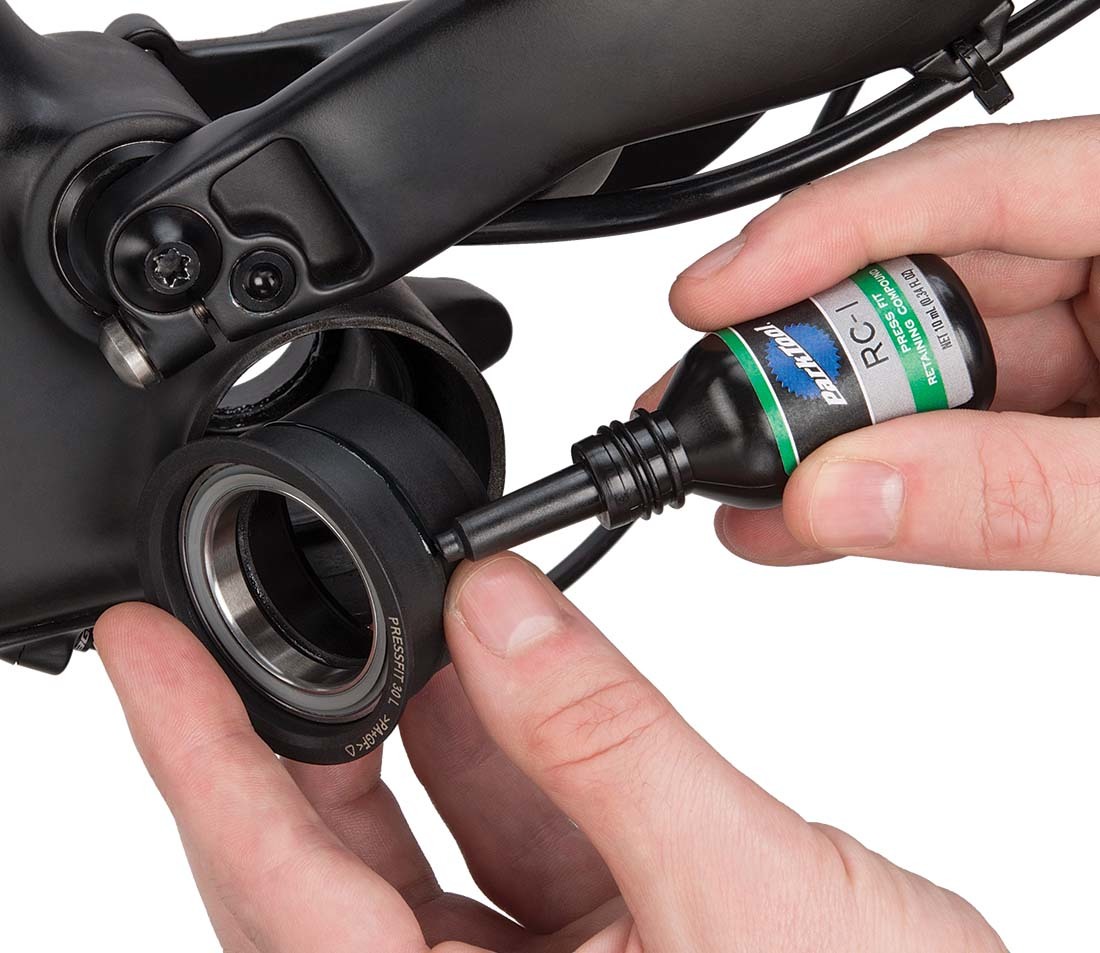
Retaining compounds are intended for press fit applications such as pressed studs. The retaining compounds tend to have a higher viscosity than the thread-locking compounds. Many retaining compounds require special technique for removal, such as excess force and or mild heat. Retaining compounds can provide a useful repair on marginal press fits, such as a headset cup that is a poor fit to the frame.
It is the habit of many mechanics to put the threadlocking compound on the external thread. This is typically not an issue, but in some cases this is not appropriate. As the parts are threaded together, the excess compounds backs up toward the head of the thread where it spreads about. Other parts may be inadvertently contaminated. For example, liquid compound applied to the bolt for a cantilever brake boss may end up in the brake arm pivot. The compound in this case should be applied in the internal thread, the boss itself. Additionally, use care when applying compounds in suspension shocks. Think through the process where the excess compound will go, and wipe up the excess after tightening parts.
Each threadlocker manufacturer publishes recommendations for their particular thread-locking product. Below are the Park Tool products.
- Park Tool TLR-1: a medium “service removable” strength threadlocker (water bottle cage bolts, etc.)
- Park Tool TLR-2: a high strength threadlocker (may require mild heat to help remove)
- Park Tool RC-1: a strong retaining compound (may require mild heat to help remove)
- Park Tool AP-1: a primer to assist the RC-1 in securing
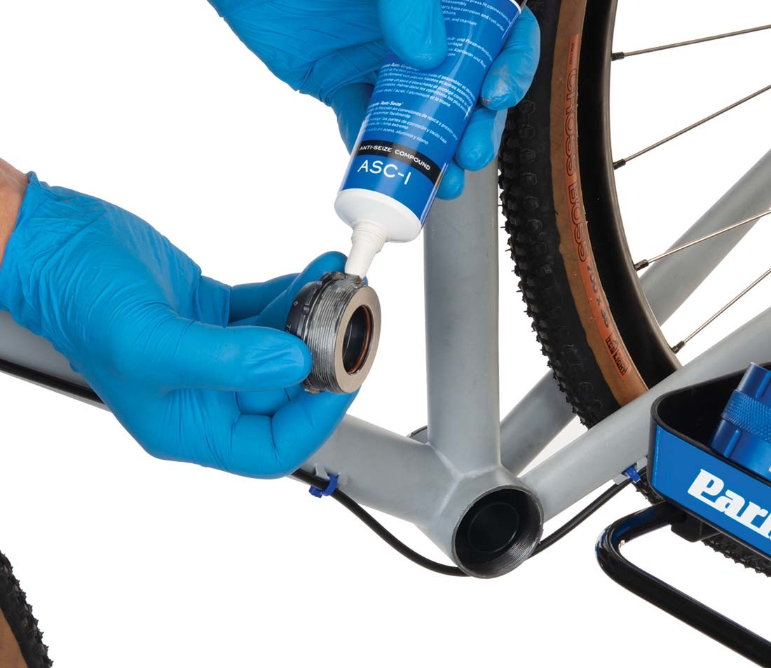
Anti-seize compounds, such as Park Tool ASC-1, are typically a mixture of finely ground materials, such as nickel, graphite, lead, copper, aluminum, zinc, and molysulfide, mixed with mineral oils. These compounds provide a good insulating layer between metals, preventing galling in the threads. These compounds provide much longer protection in adverse and wet conditions as compared to grease. The various grades and types of compounds will vary with their ability to perform at high temperatures, heavy loads, chemical exposure, and stress. However, the stress and loads experienced on the bicycle are less than the automotive uses these compounds are designed for. Use care when applying these compounds and follow the safety directions of the manufacturers.
Washers, Locking Washers, and Safety Wire
Washers are often used with threaded fasteners. The washer distributes the stress around the bolted joint. Additionally, the washer reduces friction as the bolt turns. Generally, it is best to have the washer under the turning part of the fastener, either the nut or the head. An example of washer use is under the head of the crank bolt. The washer distributes the pressure on the aluminum arm, and allows the bolt to tighten fully.
So called “lockwashers” typically do not have a flat surface, but use a deformed or star shaped surface. The concept is that the washer will “bite” into the joint material and help in preventing any loosening. A “split lockwasher” applies a mild push to nut and bolt as it is compressed, which in theory helps hold the fastener. If the thread is very poorly tightened, a lockwasher may help in further loosening. However, lockwashers add nothing in terms of “holding power” to a joint that is fully tightened. The pre-load of a fully tightened bolt far exceeds the stress added by a lockwasher.
Safety-wire is thin wire that is used to hold fasteners in place. This is a useful technique to prevent damage from a bolt backing out and striking other machinery. The aircraft and automotive racing service industries have used safety-wire extensively. A bolt knocking about an engine compartment would prove damaging. The bolt head or shank is drilled with a hole. Wire is passed through the hole and routed so tension is maintained. This thin wire does not, however, keep the bolt from loosening. The purpose is simply to keep the bolt in place if it were to loosen.
Bicycle Industry Threads
The bicycle industry has a long history of using many different thread standards. Both fractional and metric sizes are in use. Some threads are also used almost exclusively in the bicycle industry. Below is a table of some of the threads and their uses. This table is not intended to be complete and exhaustive. Always measure diameter and pitch when possible to determine threading.
| Nominal Thread Size | Example of Bicycle Uses |
|---|---|
| 2.2 mm x 56 TPI | Common 2 mm spoke threading |
| M3 x 0.5 | Dropout adjustment screws, some derailleur hardware, accessory hardware |
| M4 x 0.7 | Some derailleur limit screws (DIN standard) |
| M4 x 0.75 | Common derailleur limit screw (JIS standard) |
| M5 x 0.8 | Many uses on bicycles, including derailleur wire pinch bolts/nuts, disc rotor mounting bolts, fender and racks mounts, water bottle cage bolts, and others |
| M6 x 1.0 | Many uses on bicycles, including brake caliper mounting bolts, brake pad bolts/nuts, some fender racks, some brake adjusting barrels |
| M7 x 1.0 | Some handlebar binder bolts |
| 5/16 inch x 24 TPI | Front hubs, solid axle, less expensive bikes |
| M8 x 1.0 | Square-type crank bolts, front solid axle hubs, suspension system hardware |
| M8 x 1.25 | Stem hardware, stud type crank nuts, suspension hardware |
| M8 x 0.75 | Chainring bolt |
| M9 x 1.0 | Front hubs, quick-release, Asian manufacturer |
| 9 mm x 26 TPI | Front hubs, Campagnolo® |
| 3/8 inch x 24 TPI | Some solid axle bikes, including coaster brake |
| 3/8 inch x 26 TPI | Solid rear axle |
| M10 x 1.0 | Most quick-release rear axles, derailleur mounting bolts, brake lever adjusting barrels |
| 10 mm x 26 TPI | Rear axle, quick-release, Campganolo® |
| M12 x 1.0 | Some spline crankset bolts |
| 1/2 inch x 20 TPI | Pedal threads, one-piece cranks |
| 9/16 inch x 20 TPI | Pedal threads- common three piece cranks |
| M14 x 1.0 | Oversized frestyle axles |
| M15 x 1.0 | Crank bolt, Octalink® and ISIS Drive® |
| 1 inch x 24 TPI | Threaded headset, one-inch standard |
| 1 1/8 inch x 26 TPI | Threaded headset, 1 1/8 inch standard |
| 1 1/4 inch x 26 TPI | Threaded headset, 1 1/4 inch standard |
| 1.37 inch x 24 TPI | Bottom brackets, ISO/English/BSC, and threaded freewheel hubs |
| 1 3/8 inch x 26 TPI | Bottom brackets, older “Raleigh” three speeds |
| M36 x 24 TPI | Italian threaded bottom brackets |
| M47 x 1.0 | T47 threaded bottom brackets |
Related articles
Torque Specifications and Concepts View Article
Cutter Selection Guide for Reaming, Tapping & Facing View Article
Bottom Bracket Tapping, Threading, Chasing, and Facing View Article
The Park Tool Guide to Bicycle Lubricants and Compounds View Article