Rear Derailleur Hanger Alignment
How to measure and correct alignment of the derailleur hanger, a common source of bicycle shifting issues.
Getting Started
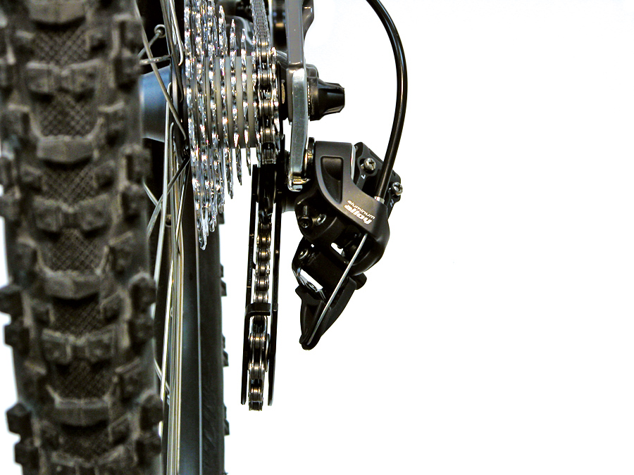
The derailleur hanger is a common culprit for mysterious shifting issues. This is in part because hangers are actually designed to bend easily. When there is an impact to the derailleur — for example, a crash, a fall, or rough handling around a rack or other obstacle — the hanger sustains the damage, protecting the more-expensive derailleur and frame. Unfortunately, this will often cause misalignment of the derailleur, resulting in poor shifting performance. This misalignment can generally not be accounted for by making adjustments to the indexing or limit screws — it will need to be addressed directly.
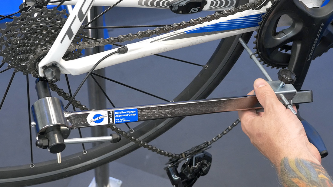
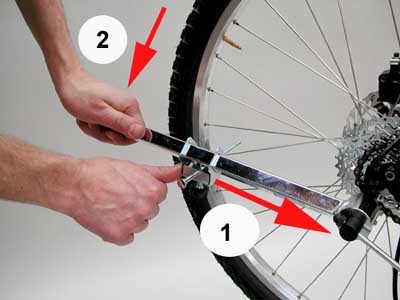
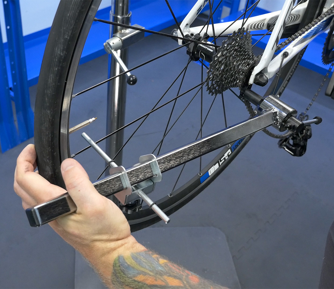
Fortunately, it is often possible to re-align most derailleur hangers using a tool built for that very purpose. A derailleur hanger alignment gauge such as the Park Tool DAG-2.2 or DAG-3 effectively extends the plane of the hanger face, allowing it to be compared to the plane of the wheel
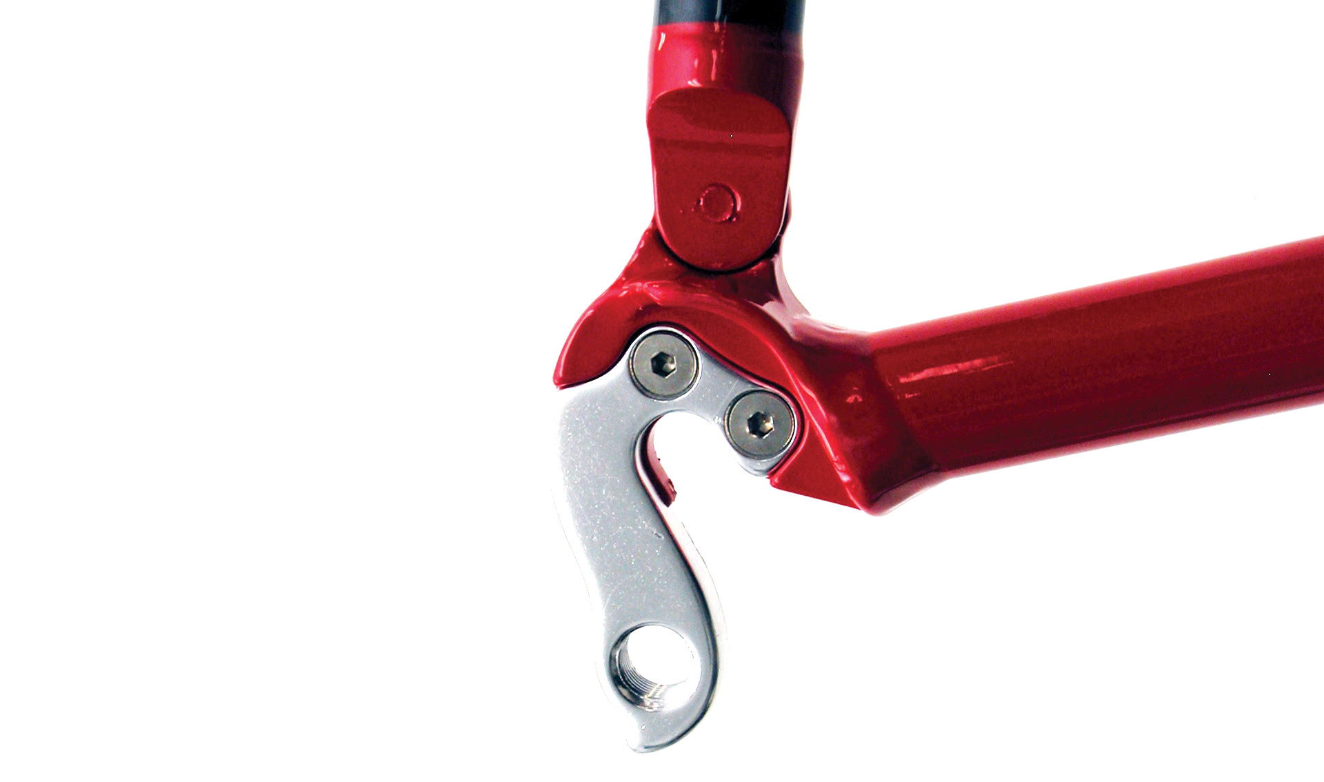
Riding does not create much stress on the hanger, so if a hanger survives a repair by bending, it will hold up under normal riding conditions. If a hanger has been subject to repeated bending from impact or attempted realignment, it may fail during the alignment process. In that case, you will need to look into replacement. This is obviously not possible for frames with integrated hangers, so exercise extreme care when undergoing this process on these types of frames.
Derailleur Hanger Alignment
This process assumes use of the Park Tool DAG-2.2 or DAG-3 Derailleur Hanger Alignment Gauge.
Begin by mounting the bike in a repair stand with the wheels level as the bike would appear on flat ground. Check that the rear wheel is mounted straight in the frame. The wheel does not need to be dished or true for use of the tool. Remove the rear derailleur. Install DAG and tighten handle. NOTE: If hanger threads seem damaged, remove the DAG. Chase and clean the threads using the TAP-10 — see Derailleur Hanger Thread Repair.
The basic outline of this process involves setting the position of the DAG indicator at one position on the rim, comparing that position against the same point on the rim when rotated 180 degrees, and making small, incremental adjustments as necessary.
Rotate the tool to the 3 o’clock position. Rotate the valve stem to the 3 o’clock position as well. Using this point on the rim as a constant reference when checking the hanger takes wheel dish and trueness out of the equation, ensuring a consistent reading.
Move the indicator of the alignment tool to contact the rim.
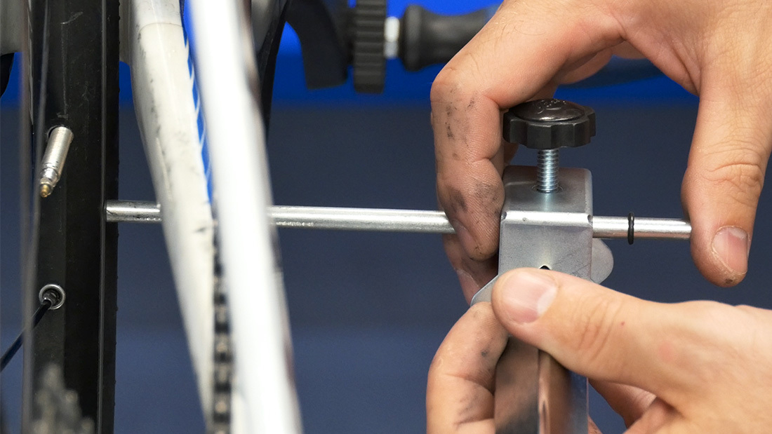
We will compare this measurement to the 9 o’clock position. For the DAG-2 and DAG-2.2, slide the indicator bracket toward the hub before rotating arm. This prevents the indicator from begin forced against the rim. For the DAG-3, simply pivot the indicator out of the way.
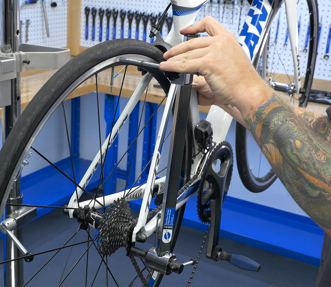
Rotate the tool and valve stem 180 degrees to the 9 o’clock position. Slide or pivot the indicator to the same point measured in the first step.
There are 3 possible results:
Result A: The indicator is less than 3 millimeters away from the rim. The hanger is aligned horizontally. Move on to vertical alignment.
Result B: The indicator is away from the rim some distance — larger than 3 mm. The hanger is misaligned.
Result C: The indicator strikes inside the rim. The hanger is misaligned.
It is easier to determine the error by seeing a gap between rim and gauge, so if you got result C, reset the tool. Contact the indicator to the rim at the 9:00 position and rotate back to the 3:00 position. There will be a gap between rim and gauge.
Now that the error is sighted, it’s time to correct it. The amount of error is actually one-half the size of the gap between the indicator tip and rim. As the gap is closed, it increases at the reference point 180 degrees away. When bending the hanger, it is best to bend small in amounts and recheck. Bend a bit, recheck both sides, and then re-bend a bit more. Generally, it is best by having the DAG arm next to the chainstay. This allows you to use the stay for leverage and control the amount of bending either inward or out. Repeat bending and checking until the gap is less than 3 mm. Use a 3 mm hex wrench as a “go/no-go” gauge.
After achieving horizontal alignment, move on to check the vertical alignment. Set the indicator to the rim at the 6:00 position, then check at 12:00 position.
Again, bend only one-half the amount of gap. Reset the indicator and re-measure after each bending of the hanger. When the gap is less than 3 mm, keep the same setting and check the 9:00 position. If three points 90 degrees apart are within 3 mm, the hanger is aligned. Continue aligning as necessary.
After aligning the derailleur hanger, it will be necessary to recheck all rear derailleur adjustments, including limit screw and index settings. See Rear Derailleur Adjustment.
Racks, Fenders, or Other Obstacles
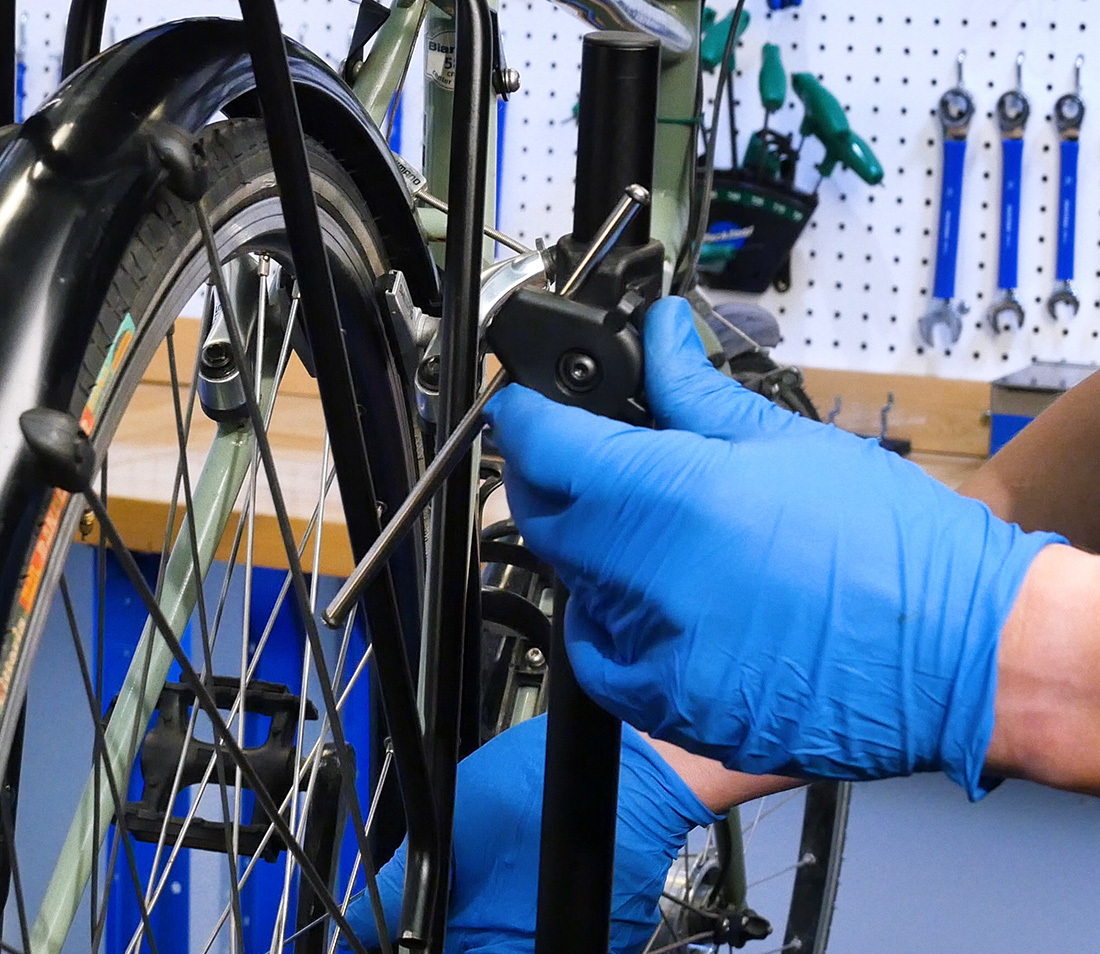
There may be fenders, racks or other situations where it the indicator is blocked from rotating to the necessary measurement positions.
When using the DAG-3, simply pivot the indicator out of the way.
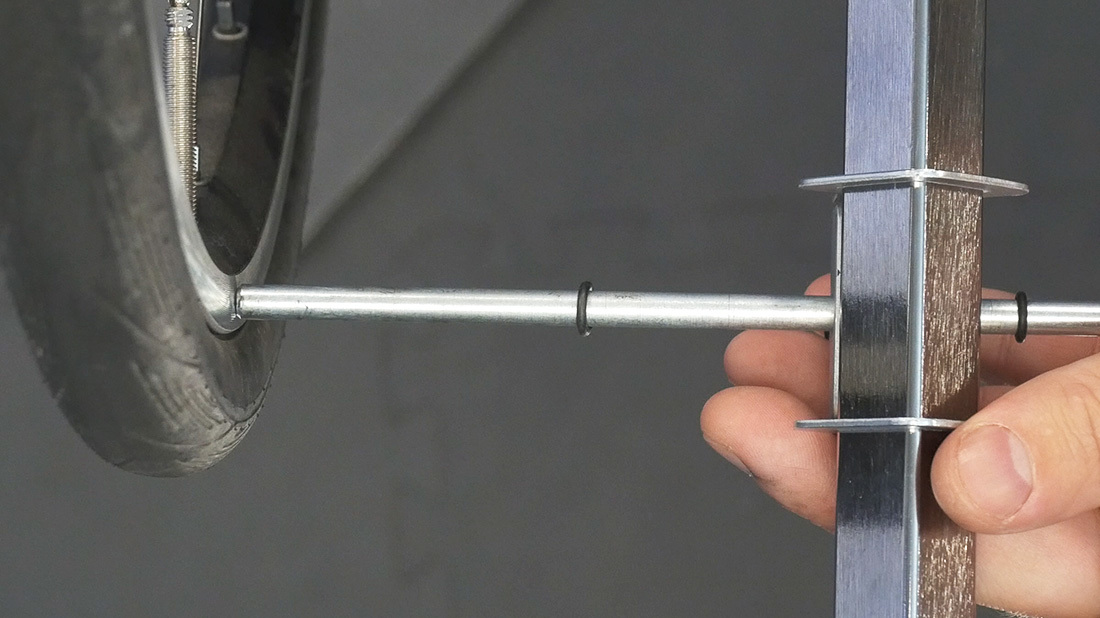
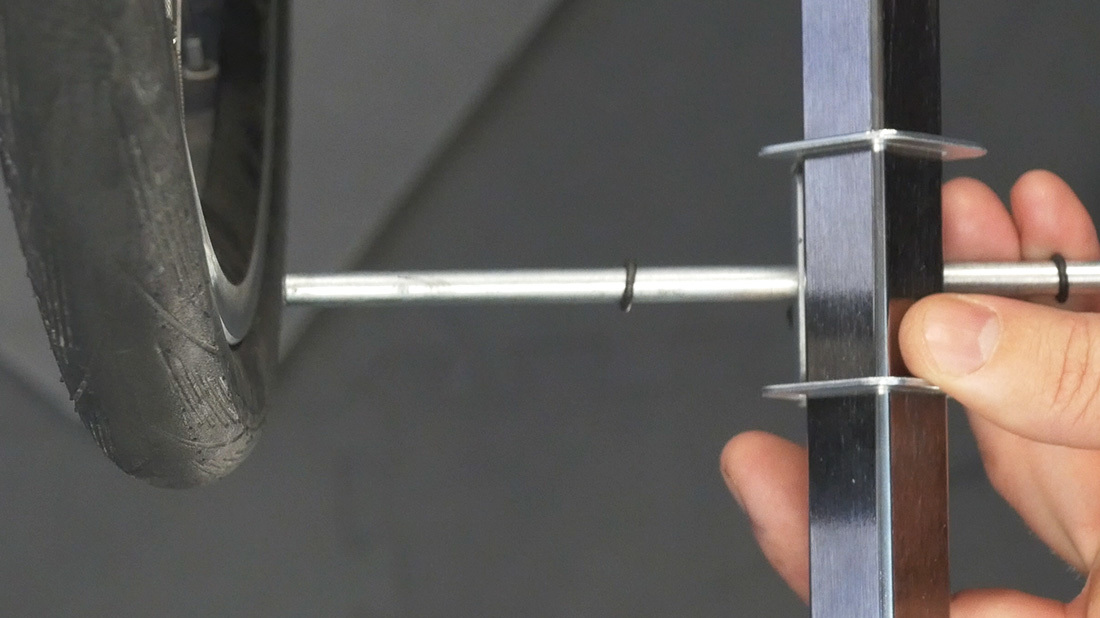
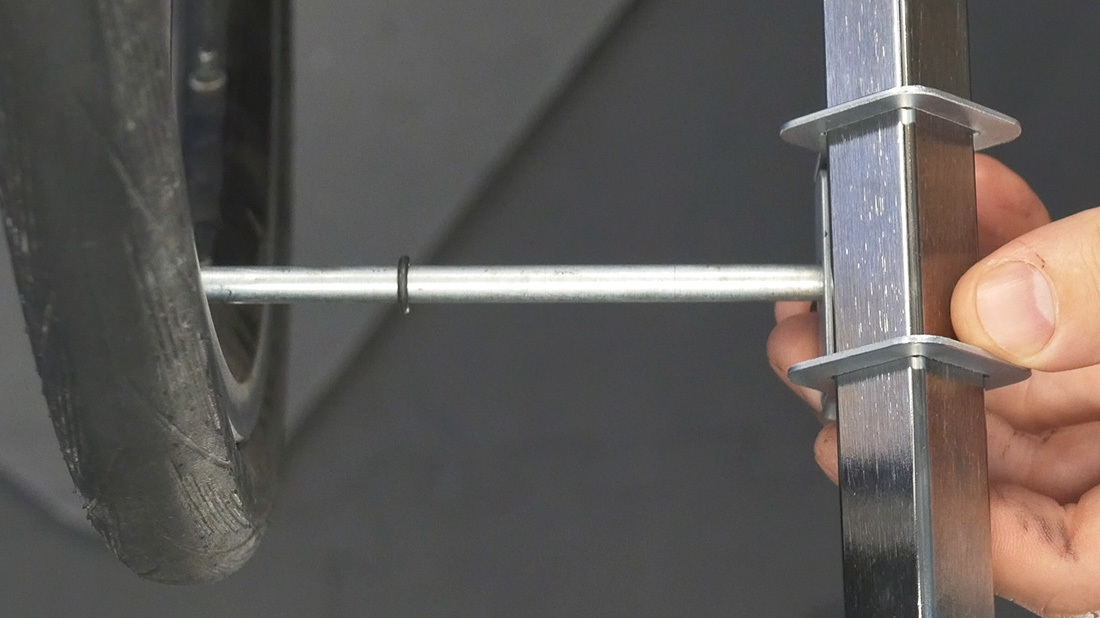
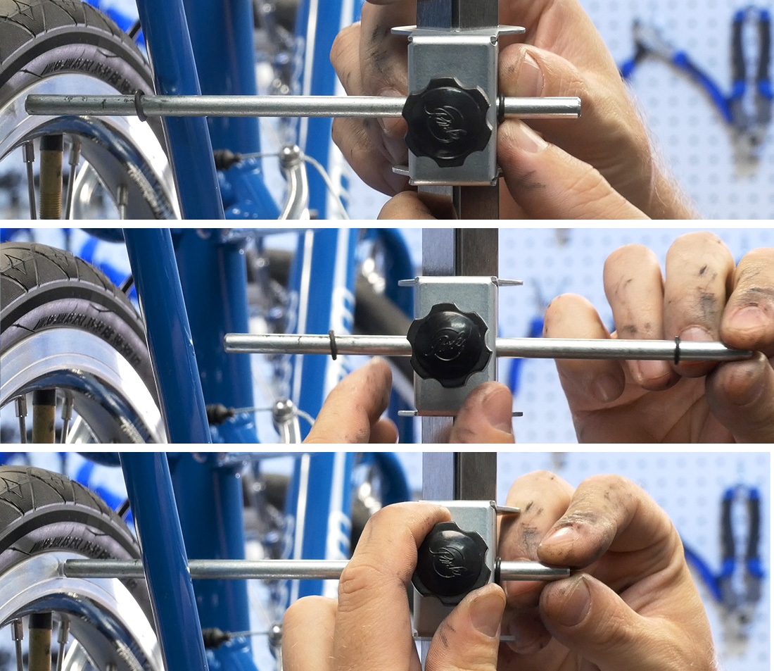
The DAG-2.2 features O-rings on the indicator which can be used as position markers.
Push the outer O-ring to the indicator. This marks the position of the gauge relative to the slider.
When the indicator cannot pass by a frame stay, fender stay, or rack, loosen the indicator knob and pull the indicator back to clear.
Return the indicator to its original position using the O-ring as a reference.
Related articles
Derailleur Hanger Replacement View Article
Rear Derailleur Adjustment View Article
Rear Derailleur Overhaul View Article
Front Derailleur Adjustment View Article
Frame Alignment View Article
Dropout Alignment View Article
Shift Levers / Shifters View Article