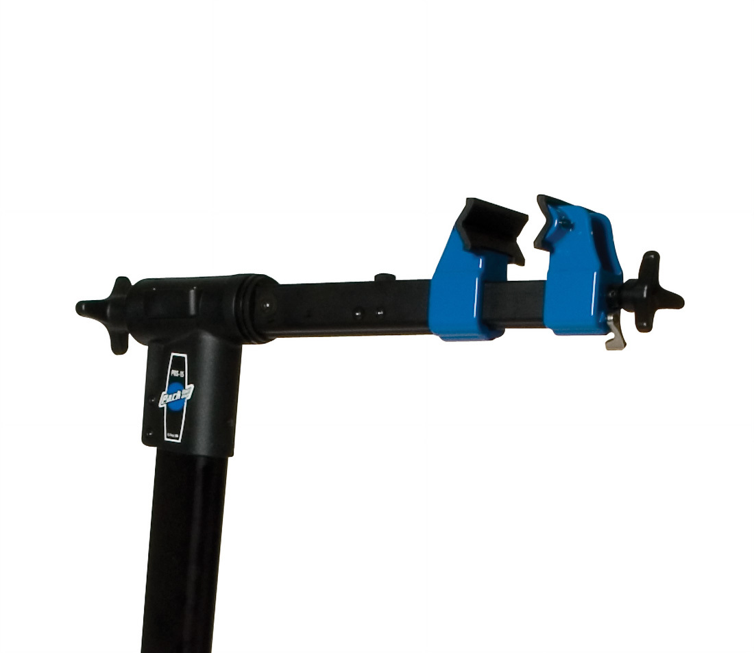
100-4X, 100-15X & 100-6X, and PRS-15 Service
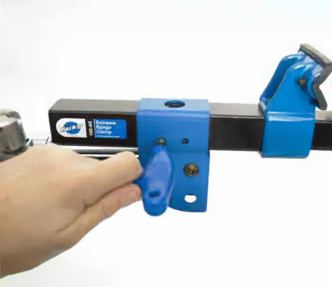
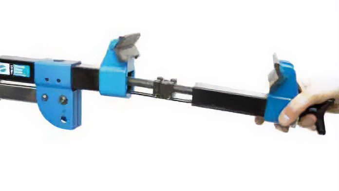
This article will discuss the service of the 100-4X and 100-15X Extreme Range Clamps. The 100-4X fits into the PRS-2, PRS-3 and PRS-4 Repair Stands. The 100-15X clamp is used on the PRS-15 repair stand. The common service of these clamps it to lubricate the moving parts. Instructions here are written assuming the clamp is positioned so the jaws are horizontal to the ground.
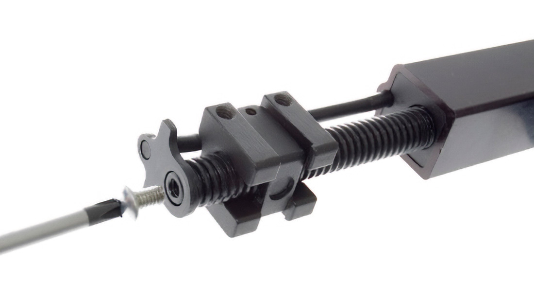
100-4X and 100-15X Sliding Body Removal and Lubrication
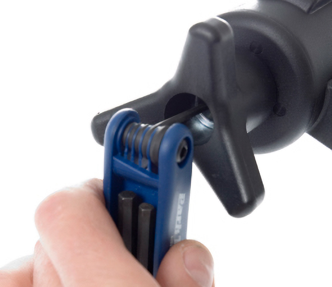
- Remove the knurled spring cap at the top of the main body. Use care not to lose spring positioned under the cap. Remove the four screws located adjacent to the knurled cap on the main body using a 5/32 inch (4 mm) hex wrench. There are two screws on the left side and two on the right side.
- Pull sliding body and remove it from the main body. Grease the full length of the threaded acme rod and the half nut cam shaft.
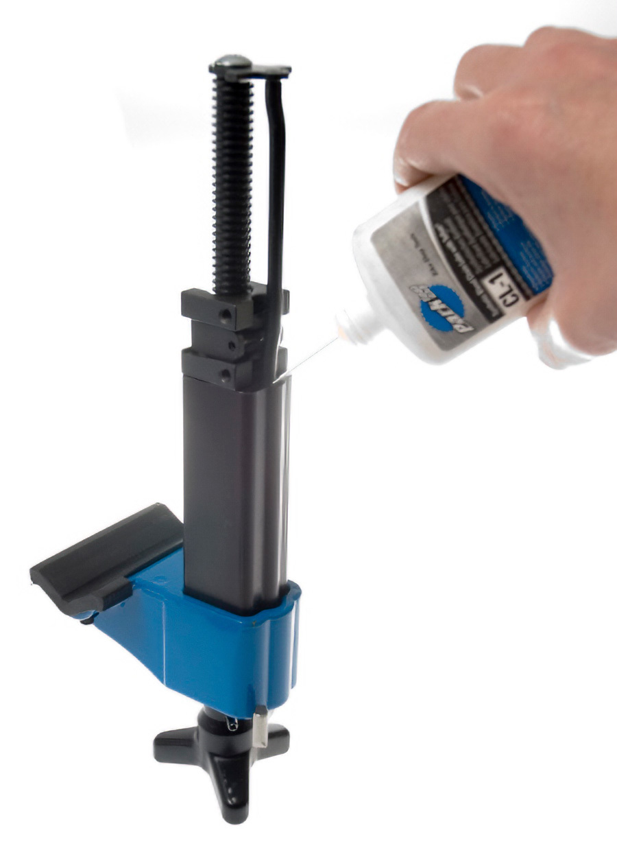
- Hold the sliding body vertically with the threaded acme rod facing upward and drip a liquid lubrication such as CL-1 down the cam shaft. This will lubricate the cam shaft as well and the cam lever.
- To assemble the clamp, adjust half nut assembly toward the far end of the acme rod. Install sliding body assembly into main body. Position half nut assembly so threaded holes align with holes in main body. Install and tighten the 4 main body screws.
- Install knurled spring cap with spring into top of main body and tighten.
- Check security of screw holding sliding jaw to sliding body.
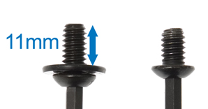
Note on Sliding Jaw Screw: It is important that the screw holding the sliding jaw to the slider is secure. If the sliding jaw is loose on sliding body, it may result in the cam lever being slow to release. Check that the screw is secure. If the screw appears not to tighten, there may be a partial thread failure in the sliding body. Remove the screw and check the screw length. There should be 7/16-inch of thread length (11mm). This is equal to a count of 9 threads. If screw is shorter then this, use a longer screw of 1/4-inch by 20 TPI (threads per inch). Use washers to adjust the thread length until there are 11mm of exposed thread. Install and secure new screw using a thread locker such as Loctite® #242.
Cam Replacement or Other Internal Service
- Remove the sliding body from main body as described above.
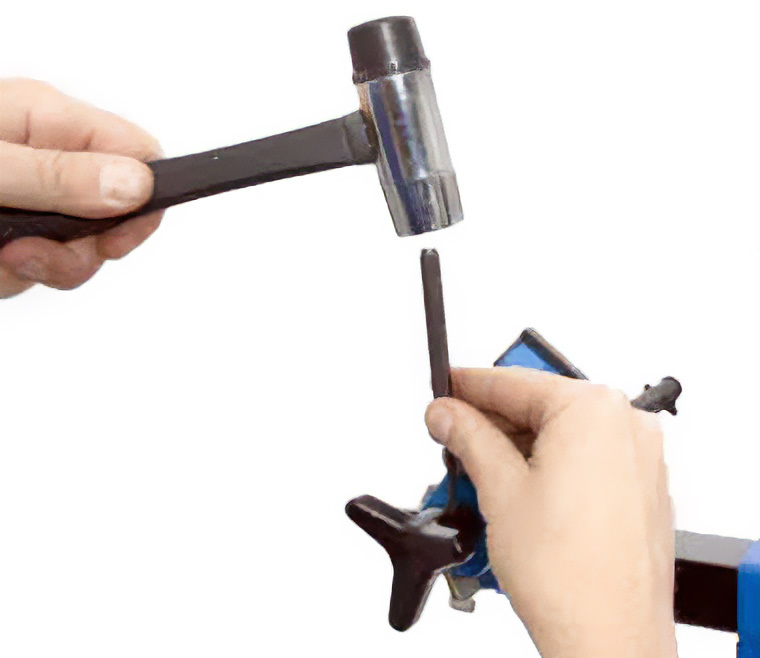
- Drive the spring pin from the handle using a 3/16-inch pin punch. Remove the handle and thrust washer behind the handle.
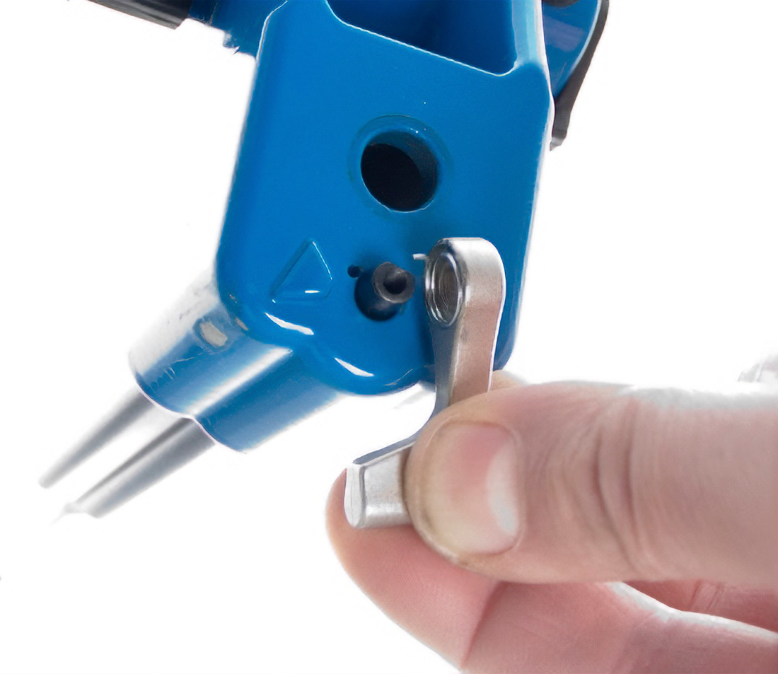
- Remove the cam lever screw and cam lever. There is a small spring between the lever and clamp body. Remove the lever with care.
- Loosen sliding jaw screw from sliding jaw and pull jaw from sliding body. (NOTE: Check screw length and see note below on sliding jaw.)
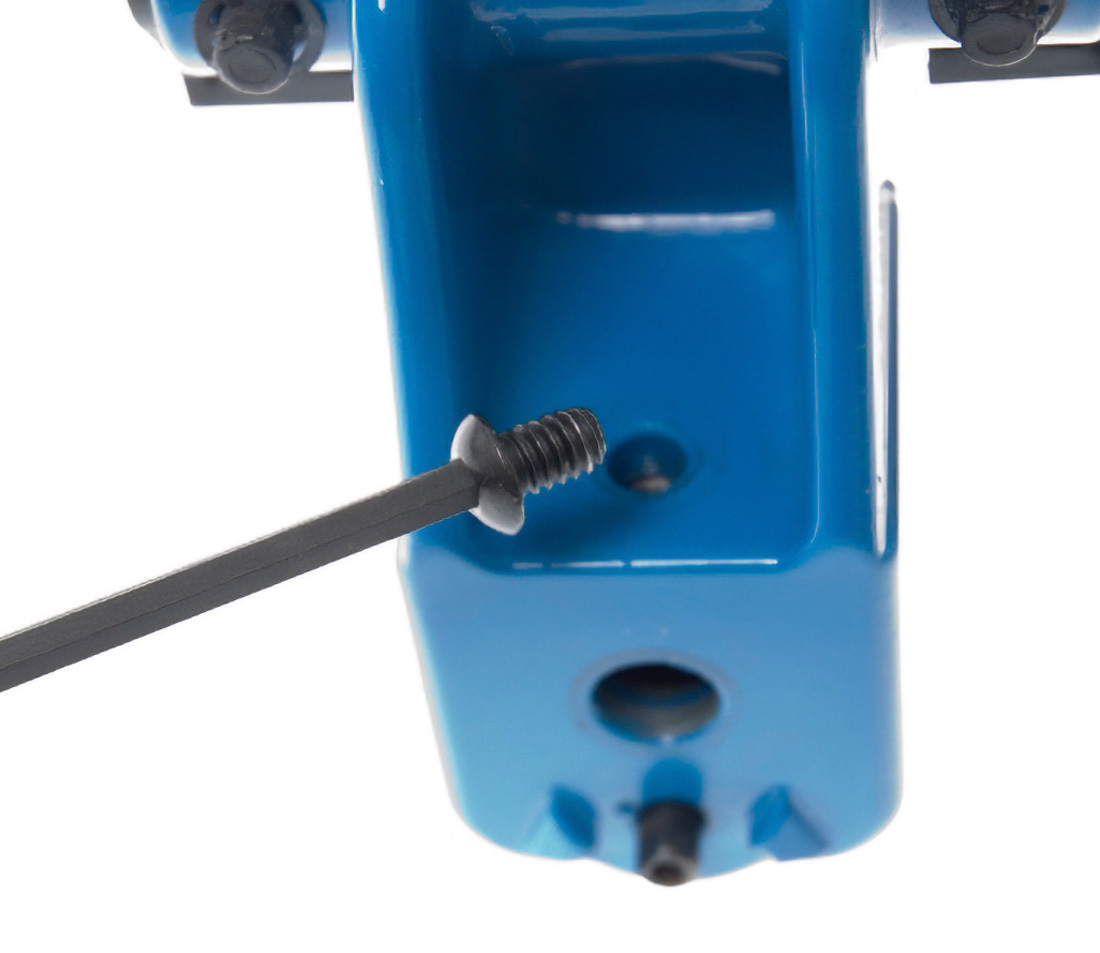
- Remove the acme rod screw from the back of the acme rod, and remove the slide plate.
- Lift the half nut and pull the half nut assembly from the acme rod.
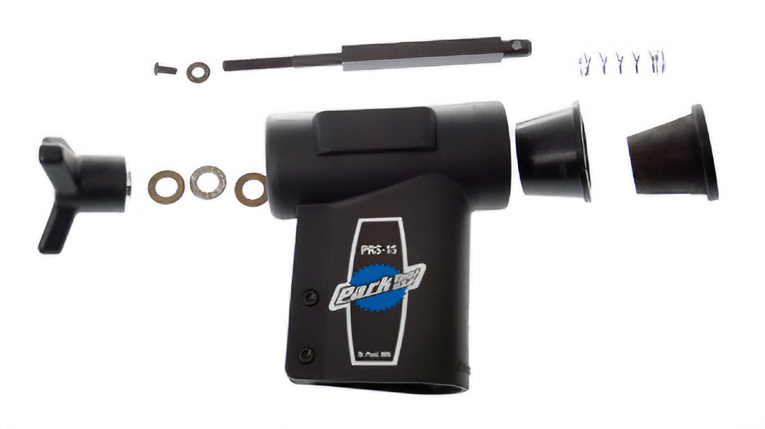
- Remove the cam shaft, remove E-clip from front of the shaft. Remove the cam from the sliding body.
ASSEMBLY
When assembling the clamp, grease all moving parts.
- Install the cam back into the sliding body and install the E-clip onto the end of the cam. The E-clip end of the cam faces the open end of the sliding rod.
- Install the sliding jaw onto the sliding body, inserting the end of the cam through the lower hole of the jaw body. Install and tighten the jaw screw.
Note on Sliding Jaw Screw: It is important that the screw holding the sliding jaw to the slider be secure. If the sliding jaw is loose on the sliding body, it may result in the cam lever being slow to release. Check that the screw is secure. If the screw appears not to tighten, there may be a partial thread failure in the sliding body. Remove the screw and check the screw length. There should be 7/16-inch of thread length (11mm). This is equal to a count of 9 threads. If screw is shorter then this, use a longer screw of 1/4-inch by 20 TPI (threads per inch). Use washers to adjust the thread length until there are 11mm of exposed thread. Install and secure new screw using a thread locker such as Loctite® #242.
- Install the cam lever. Note “D” shape inside lever and “D” shape at end of cam shaft. The flat of the lever must mate to flat of cam end. Rotate cam end until flat faces the small spring hole in jaw body. Place either end of the spring in lever spring hole. Use some grease inside lever to help hold spring in place. Install spring end into spring hole of jaw body, and mate lever onto end of cam. Push lever onto cam and install lever screw with some mild threadlocker.
- Install threaded acme rod through sliding body. Test jaw body screw length by turning acme rod. Rod should insert fully through jaw body and turn freely. If screw is too long, acme rod may bind or not fully insert. Use an additional washer under jaw screw and test rod again.
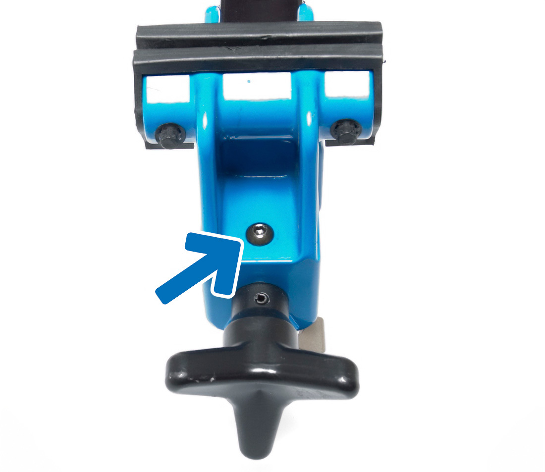
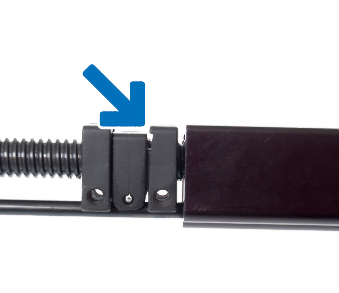
- Install half nut assembly onto acme rod. Holes in assembly should face toward cam. The half nut assembly has two side pieces. There is a notch shape on one side. Note arrow in image below. This notch should face the sliding body.
- Install slide plate and screw at end of acme rod and end of cam. Engage cam through lower hole in plate. A mild thread locker is recommended for this screw. To keep acme rod from turning, insert hex wrench through far end of rod and tighten screw.
- Place thrust washer on end of acme rod adjacent to sliding jaw. Install handle and drive spring pin into handle and acme rod.
- Adjust half nut assembly toward the end of the acme rod. Install sliding body assembly back into main body. Position half nut assembly so threaded holes align with holes in main body. Install and tighten main body screws.
- Install knurled spring cap with spring into top of main body and tighten. Clamp is ready to use.
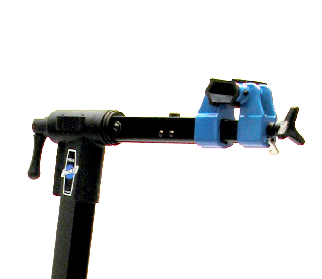
Replacing 100-15X Clamp
- Loosen the top tube knob fully to disengage clamp from top tube.
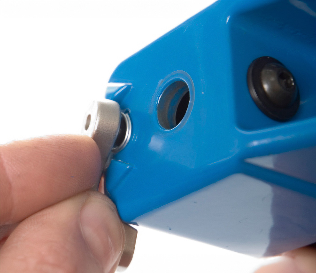
- Remove the two body pivots screws the end of the clamp using a 3/16-inch hex wrench.
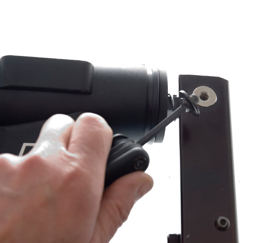
- Use a small punch to drive the pin out from the center of the body pivot. Spring at the end of the main clamp screw will be loose. Use care not to lose spring.
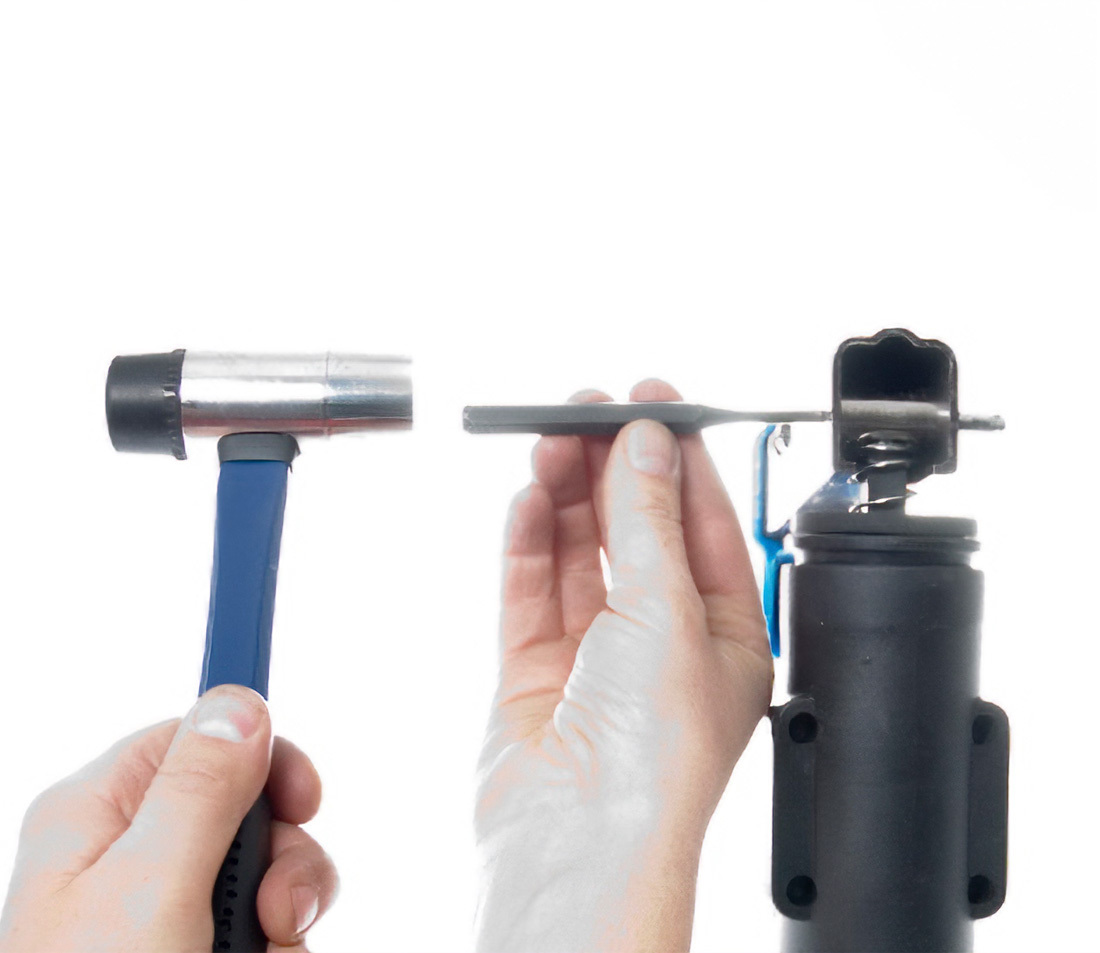
- Remove body pivot from the old clamp and install into the new clamp.
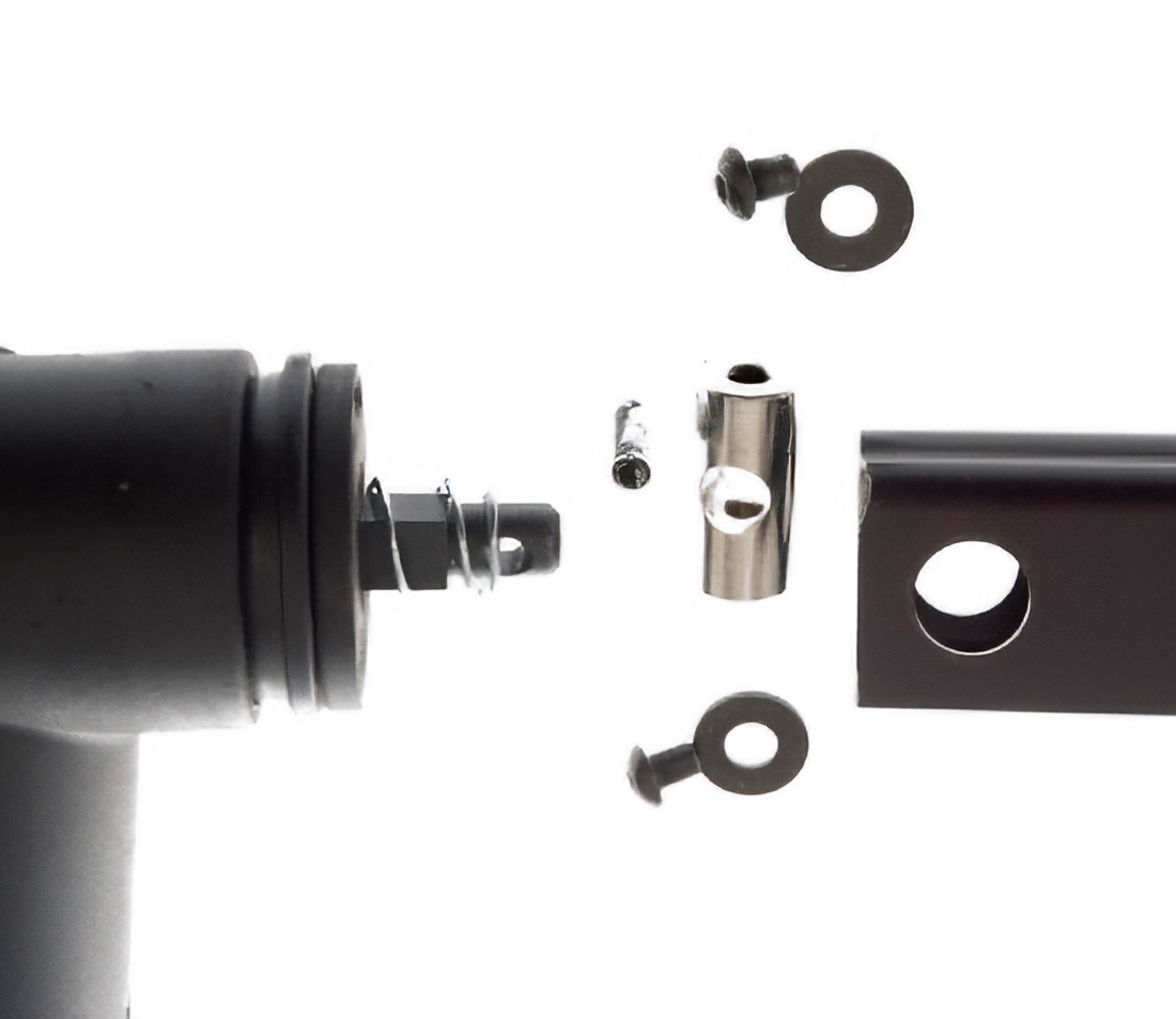
- Install clamp onto end of main clamp screw and align hole in screw with hold in body pivot. Push or tap pin into place. Center pin in pivot.
- Install both body pivots screws and tighten.
Replacing Main Clamp Screw on PRS-15
Begin by first removing the clamp from the main clamp screw and top tube as described above in Replacing 100-15X Clamp.
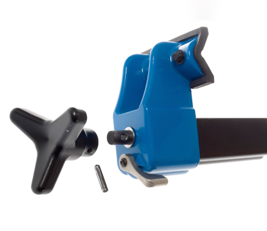
There are two versions of PRS-15 top tube and clamp knob. The first generation has a longer swing handle at the end of the top tube. With this version, begin by removing the swing handle. There will be a screw seen inside the handle fitting, and from this point the two versions are the same for service.
Later versions use a triangular knob at the end of the top tube.
- For either version, loosen and remove the top tube knob screw and washer. NOTE: This is a left-hand threaded screw and is installed with a thread locker. Use mild heat as from a hair dryer or air gun. Remove by turning clockwise.
- Unthread knob completely from main clamp screw.
- Remove main clamp screw from top tube.
- Install new main clamp screw. Reverse disassembly instructions to assemble. Install clamp as described above in Replacing 100-15X Clamp.
Related articles
1951-15 Adapter Stud Installation for PRS-15 View Article