BMX Freestyle Detangler Adjustment
This article will discuss the "detangler" headset and brake system. The detangler is a linkage system used on BMX freestyle bikes that allow the front wheel and bars to rotate 360 degrees without the brake cables tangling or wrapping around the stem (See Figure 1).
Getting Started
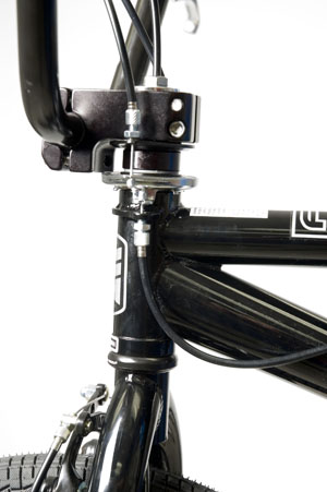
Figure 1
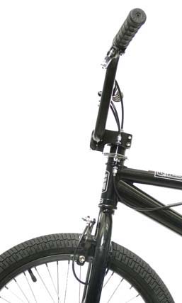
Figure 2
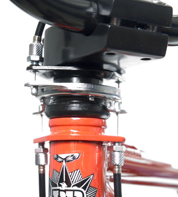
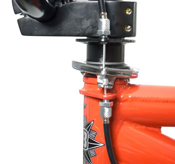
The front brake cable fits through a hole in the middle of the steering column (Figure 2). A special “star fangled nut” or headset compression plug must have a hole for the front cable housing. It housing exits under the fork crown and attaches to the front brake.
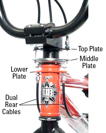
A typical detangler system consists of three series of plates (Figure 3). There will be a lower plate which is fixed to the frame. In some models the lower plate welded to the frame. The upper plate is fixed to the stem, and turns with the stem. The middle plate consists of a two piece bearing system. This middle plate has attachments for the cable ends, and will move up and down on the steering column to pull the rear brake cable. The bearings allow the middle plate to rotate 360-degrees.
Setup Procedure
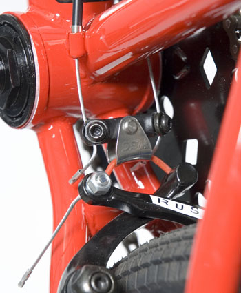
When the rear brake lever is pulled, a pair of cables from the lever pull the middle plate upward (Figure 4). The rear cables are attached to the middle plate, and these will be pulled as well.
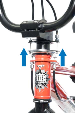
Figure 4
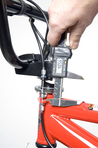
Figure 5
The spacing at the detangler is critical (Figure 5). If the distance between the upper plate and lower plate is too short, the middle plate may top out or contact the upper plate. The result will be that there will be no additional cable force transmitted to the rear caliper. Measure distance between upper and lower plates. From the inner edge of each, the distance should be generally no less then 38mm. Add headset spacers under the upper plate as necessary.
Detanglers will have two rear cables that attaching to the lower plate. However, there are different designs that route these cables to the rear brake caliper. In Figure 6, the two primary wires from the detangler are merged into one, which then attaches to a straddle wire carrier.
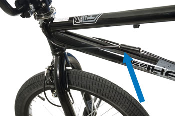
The cable system in Figure 6 runs two primary wires from the detangler. Each wire attaches directly to a pinch bolt at the caliper arm.
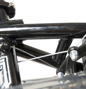
Note the cable routing in Figure 7. The cables are crossed as the wires approach the caliper arm. This allows the cable to pull the arm close to 90-degrees from the swing of the arm. This is the most effective method to pull the arm and apply force to the rim. It is important however the wires do not rub one another where they cross.
The system in the Figure 8 also uses dual cables. This is called a DC Amplifier™ by the Ogry™ Company (registered trademarks of the Scura Speed & Technology). The brake caliper arms are connected by a straddle wire, and the straddle wire is pulled by a brace connecting to the cables. In this design, the straddle wire should generally be kept as short as possible, with just enough length to allow it to disengage. Each dual brake cable secures to its own pinch bolt.
Detangler Adjustment Procedure
The detangler needs to be adjusted so that it allows a full cable pull for the rear caliper. Additionally, the detangler should rotate smoothly when the handlebars are rotated. The detangler should not articulate or “flop” during bar rotation with or without rear brake being pulled (Figure 9).
Flop is the result of uneven cable pull between the two dual cables. There are different methods for adjusting out flop. See the note at the end of this article for a more detailed adjustment options.
Begin by setting all four adjusting barrels evenly (Figure 10). There are two adjusting barrels in the upper plate from the brake lever cables, and two barrel adjusters in the lower plate from the lower cable.
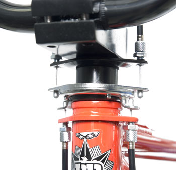
Figure 10
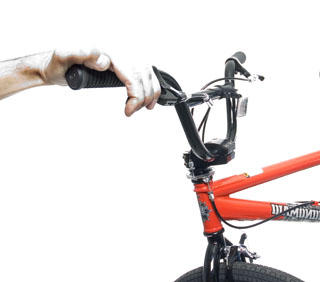
Figure 11. Pull lever and rotate bars
Rotate the handlebars and watch the middle plate. Note any sudden jerking or twisting fore-aft as the bars rotate. Also pull the brake lever firmly and repeat bar rotation (Figure 11).
If the middle plate flops, it is necessary to move the adjusting barrels. A simple technique is to select one of the four barrel adjusters and turn it, noting if you are turning it in or out of the plate. Repeat rotating the bars and note is the flop is worse or better (figure 12). If the flop is worse, return the barrel adjuster to the previous position, and adjust the other side. When the flop begins to decrease, repeat adjusting that side.