Linear Pull Brake Service
This article will discuss linear pull style brake rim calipers. Caliper attachment to the frame, pad adjustment to the rim, and pad centering and clearance will be reviewed.
Preliminary Info
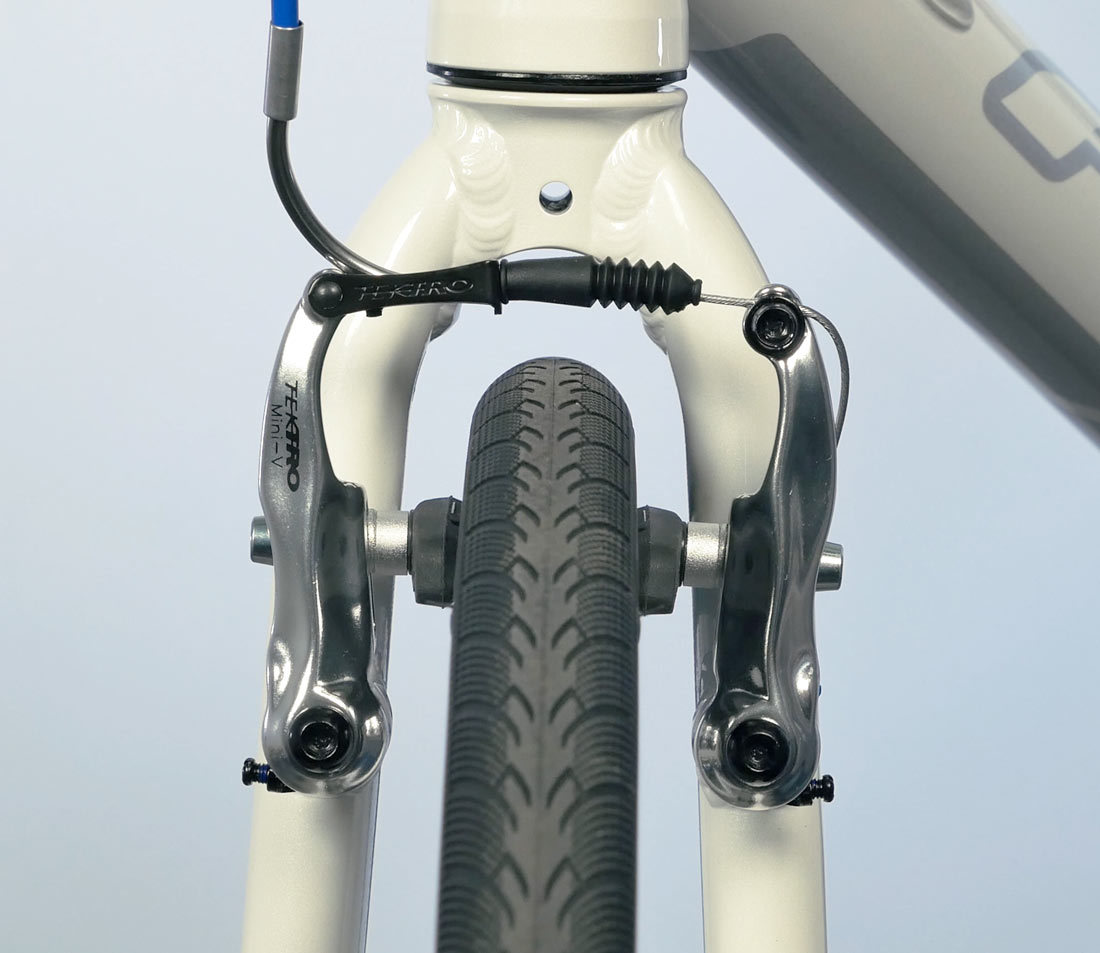
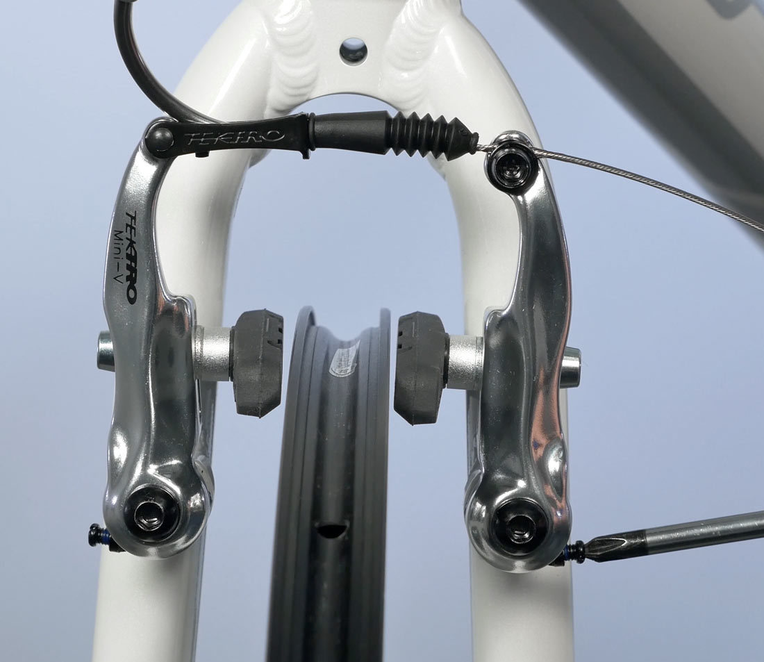
Linear pull brakes are a variation of “cantilever brakes.” Each arm pivots on a frame fitting called a “braze-on.” Like cantilevers, the pivots are located below the rim. The cable housing attaches to one arm at a linkage and “noodle.” The bare cable continues to a pinch bolt on the other arm. Pulling the cable then pulls the arms and brake pads to the rim.
Caliper Installation
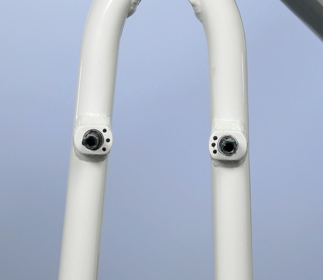
The linear pull brakes mount to the same frame fittings as the cantilever brake. The outside of this surface should get some grease to help them run smooth and not blind. The recommended thread treatment is a mild thread locker. Install the thread locker inside the thread of the fitting.
The brake calipers have a spring that will insert into one of three possible frame/fork mount fittings. The top-most fitting provides a lot of spring tension. Typically, select the middle hole and make sure that both sides are symmetrical and in the same middle hole.
Mounting bolts are threaded into each side. A typical torque for the mounting bolts is 8 Nm.
Pad Adjustment
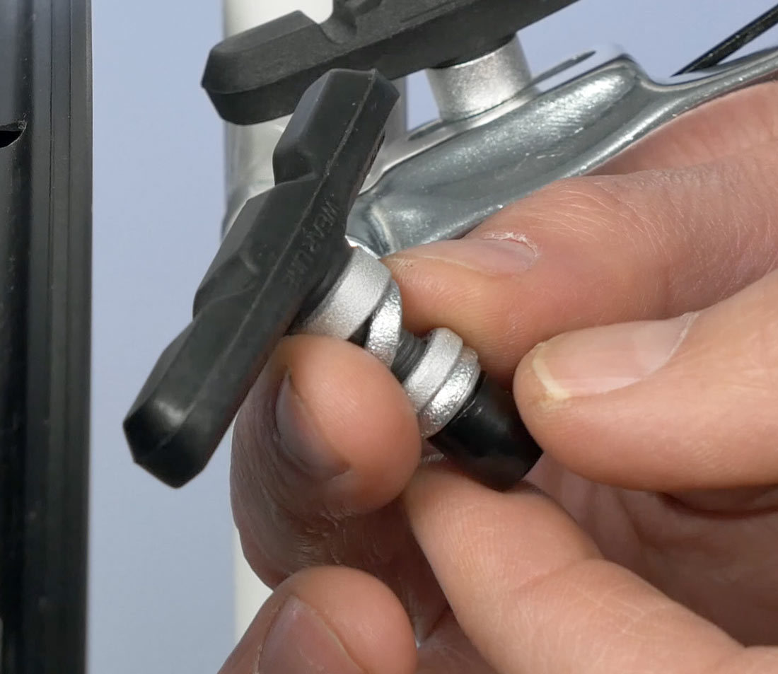
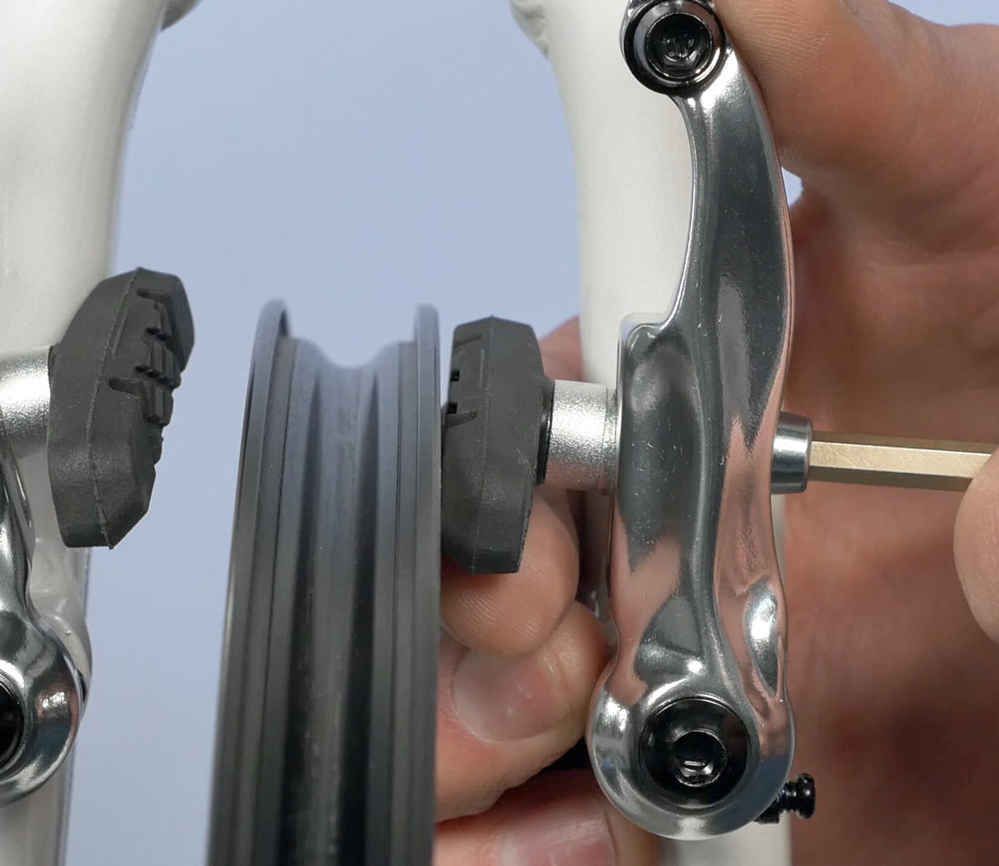
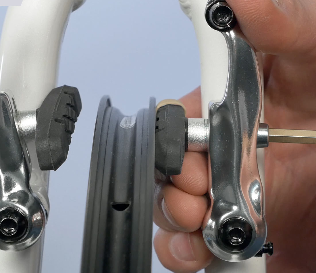
The common linear pull will have a threaded stud system. There’s a series of convex and concave washers that create a ball and socket system. This enables alignment on several planes, allowing for setting of toe, squaring the vertical face of the pad to the rim, and moving up and down in the brake arm for height. The pad setting is secured with a single nut at the back of the brake stud.
Linear pull pads should be set to the top edge of the rim braking surface, but never so high the pads would touch the tire. The linear pull the arms toward the rim on an arc coming down as they approach the rim. As the pads wear and thin, they tend to travel further down the braking surface of the rim.
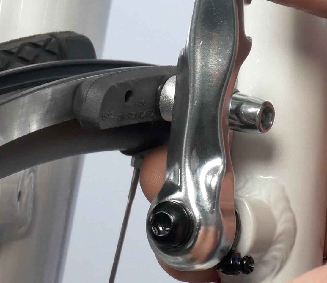
Toeing refers to setting the pad so the pad’s front edge strikes first, which tends to reduce squeal during braking. Caliper arms tend to have play in the pivots and the arms flex when the brake is applied. This may cause squealing in the brake pads. It is simplest to first ride the bike and see if the brakes squeal.
If the brakes squeal, loosen the nut and bring the wrench forward or back as needed to set toe so that the front of the pad strikes the rim first.
A second useful technique to get some toe is to put a shim at the back edge of the pad. Place a shim at the back of the pad to account for toe, such as a rubber band. The rubber band will push out the back of the pad and create toe in the setting.
With the pad nut loosened, apply some mild force to bring the pads to the rim. The convex-concave washers tend to align to the position of the pad stud. Secure the pad nut and repeat on the other side. Remove the shims, and there should be a slight gap at the back of each pad which is toe.
Cable Attachment
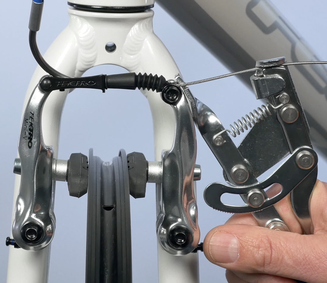
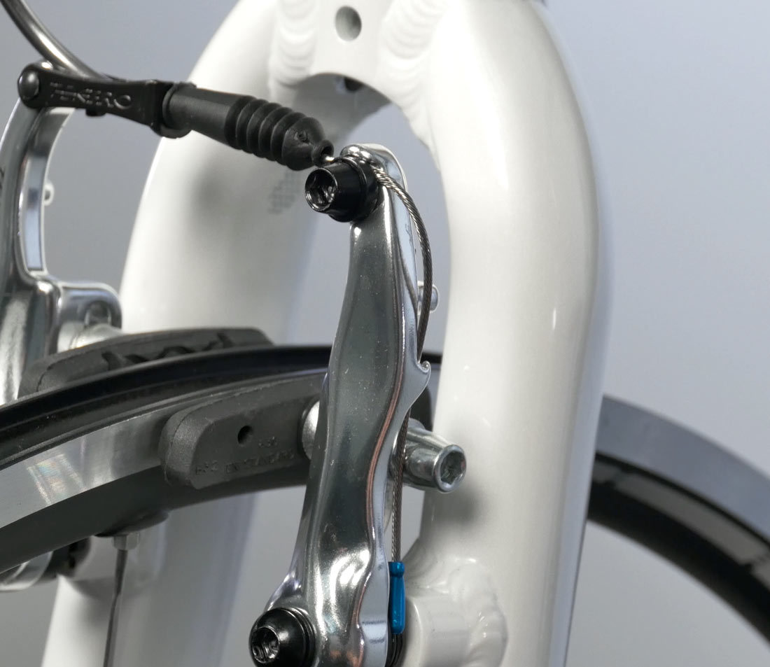
The brake cable housing will be stopped at the noodle. The linkage (noodle) holds the housing and the cable passes out to the other arm.
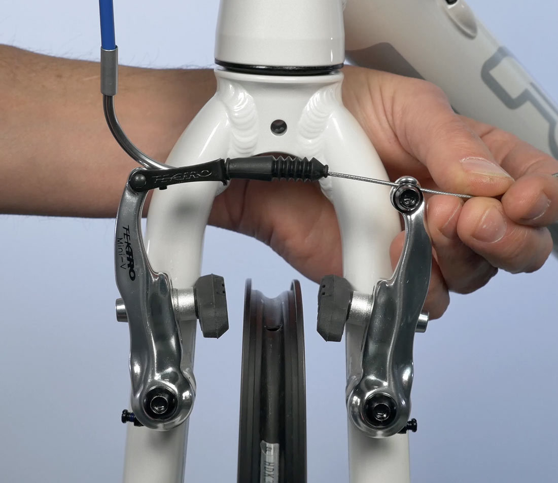
With the housing fully secured in the noodle and the noodle secured and seated in the linkage, draw the arms to the rim. Use a “fourth hand” such as the BT-2. Don’t squeeze the tool with force, just pull slack out of the system. Secure the pinch bolt.
Set Pad Clearance
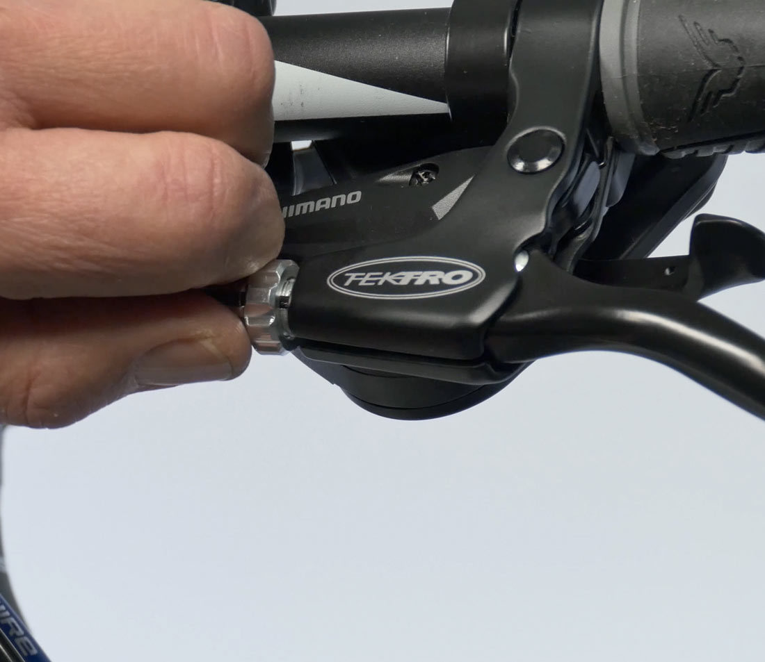
Pull the lever with force to test the pinch bolt holding the cable and settle in the housing. Set the pad clearance at the rim by the feel at the lever. Normally the setting on the front is duplicated for the same feel on the rear.
If the cable adjustment is too tight, the lever is going to pull and immediately engage. Too tight a setting will result in brake rub on the rim. Bring the barrel adjuster at the brake lever inward to give more slack.
If the cable adjustment is too loose, it may lack power. Turn the barrel adjuster out from the lever to take out slack.
Centering
Inspect the pad centering to rim. Use the set screws on the sides of the calipers to center pads to rim. The arms move together when either screw is turned. Tightening the centering screw increases the return spring tension. Loosening a centering screw relaxes the spring. Adjustments can be made from either side.
Finishing Touches
Trim the cable and install the cable end cap. Tuck cable end into brake so it does not stick out.
Related articles
Brake Pad Replacement: Rim Brakes View Article