Threaded Headset Service
This article will discuss removing the old headset, installing and adjusting a new threaded headset.
Getting Started
- Appropriate Headset Wrenches
- Appropriate Hex Wrenches for stem removal
- Race Remover: RT-1
- Headset Press: HHP-2
- Crown Race Installer: CRS-1
- Degreaser: CB-4
- Crown Race Puller: CRP-2 (other options described below in procedures)
- Measuring Caliper: DC-2
- Rags
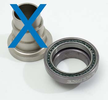
Bearings on a bicycle allow the parts to rotate relative to one another. The headset allows the fork to turn smoothly while riding. Bicycles, and all two wheeled vehicles, make small self corrections in steering while traveling forward. If the headset is pitted or worn, these corrections are not made smoothly and handling suffers. Very worn headsets tend to “lock up” when the front wheel is pointing straight. Pick up the front of the bike, and gently swing the handlebars back and forth from center. Pitting in the cups will cause the headset to stick as it passes through center position. A pitted headset should be replaced. New headsets are pressed into the frame and fork.
All bearings on a bike have some friction as they rotate. This is normal and does not affect the ride. Better quality bearing surfaces are ground smoother and will have less friction and resistance to turning. Adjustable type bearing systems use two opposing races which can be moved relative to one another. If the adjustment is too tight there will be too much pressure on the bearing surfaces and balls and the system will quickly wear out. If the adjustment is too loose there will be movement or “play” between the parts. This will cause a knocking in the bearing surfaces and again they will wear out prematurely. Generally, the bearings should be adjusted as loose as possible without play or knocking in the system.
The upper and lower bearing surfaces are connected by the steering column. The two bearing surfaces need to be parallel in order to operate smoothly. If the upper and lower surfaces of the head tube are not cut parallel, the bearings will tend to bind as the fork is rotated. This can lead to premature bearing wear and a less than desired adjustment. The head tube can become deformed by welding or simply less than adequate manufacturing techniques. The base of the fork steering column should also be cut square to the fork. If it is not properly machined, the fork crown race will not sit square to the steering column and will add to the binding effect. The head tube can be machined (faced) so the surfaces are parallel by using the HTR-1 Head Tube and Racing Tool, or the HTR-1. The fork can be machined with the CRC-1 Crown Race Cutter. This process is best left to professional mechanics.
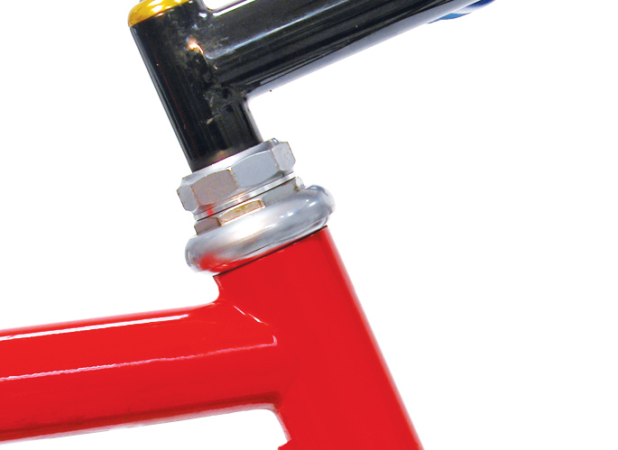
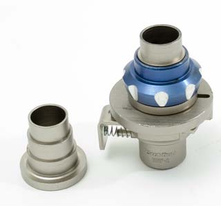
Threaded headsets consist of four bearing races, two sets of bearings, spacers and a locknut. Two bearings races are called cups and are pressed into the head tube. Generally, the more massive looking head tube cup is the lower cup of the headset. There will be one race for the fork crown. It is pressed onto the base of the steering column. The last race is threaded onto the steering column and is for bearing adjustment. This race opposes the top most head tube cup. A set of bearing is located between the adjustable race and the head tube race. Another set of bearings is located between the fork crown race and the lower head tube race. One or more spacers are placed above the threaded race and a locknut is finally threaded on top to secure the adjusting race. Threaded headsets do not rely on the stem for the bearing security or adjustment. A typical threaded headset and parts are seen below.
Headset Removal
- If possible, disconnect cables shift and brake levers. Loosen stem and remove bars and stem from steering column.
NOTE: If you are not removing bars completely, use care not to kink or damage housing when hanging bars on bike.
- Hold lower threaded race with spanner. Loosen and remove top locknut by turning counter-clockwise.
- Remove front wheel if still in place.
- Remove any washers/spacers from steering column.
- Unthread and remove threaded race. Hold fork to prevent it falling to the ground. Note orientation of bearing retainer (if any).
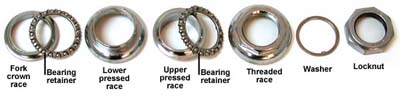
- Install Park Tool RT-1 Race Tool with small side first upward through the bottom of the headset cups. Squeeze sides of prongs and pull tool fully into head tube. Do not press with hand on bottom of tool, as prongs will close and pinch flesh. A clicking sound will be heard as tool engages head tube cup.
- Use a hammer at end of RT-1 and drive cup from head tube. Use care as cup approaches end of tube, as tool may fall to ground on last blow of the hammer.
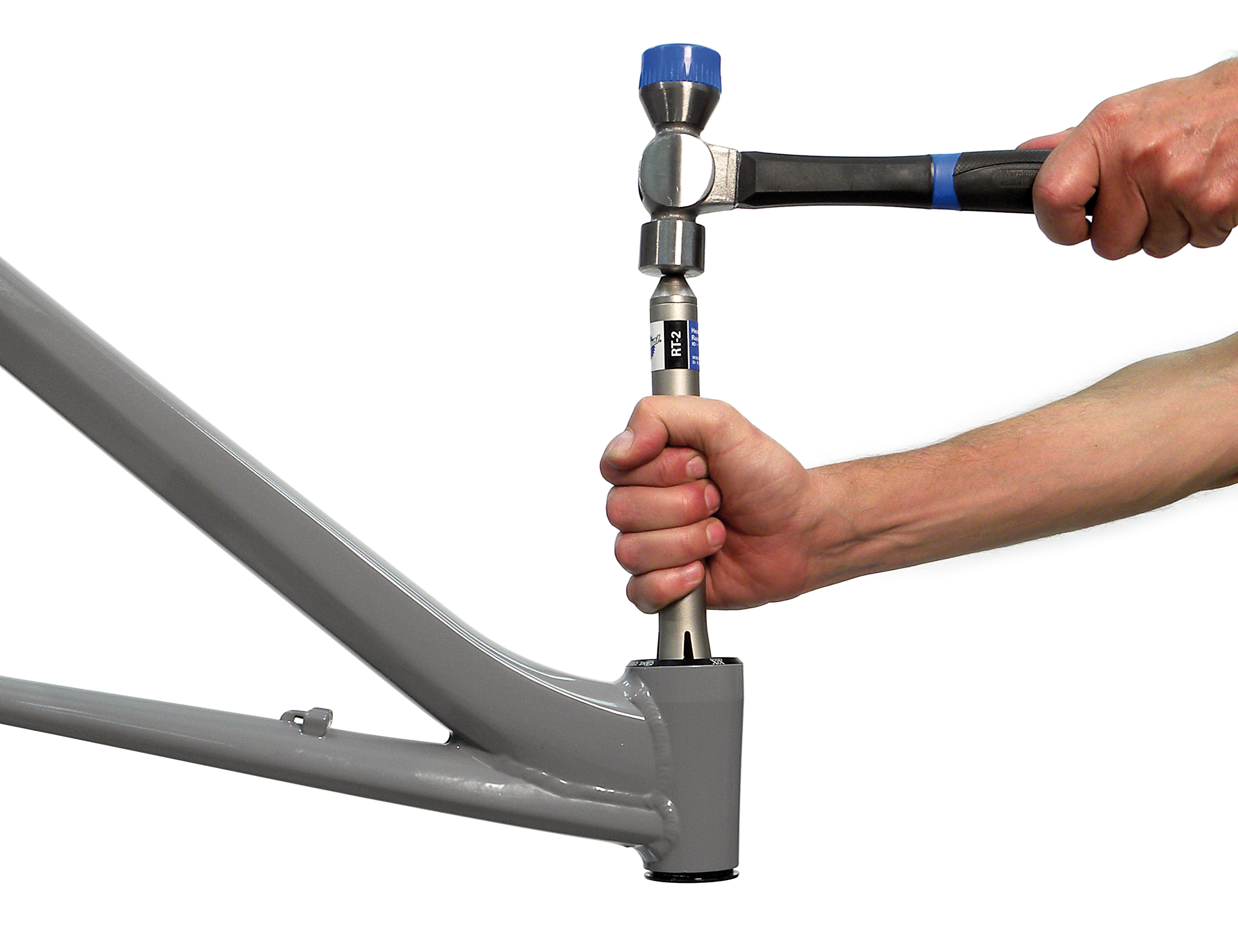
- Place RT-1 with small end first through remaining cup and remove.
- Remove fork crown race from fork. Use the Park Tool CRP-2. For specific use of CRP-2 see Crown Race Removal.
- An optional procedure to the above is to drive the race off using a punch and hammer. In some cases this may scar the fork and crown race.
Headset Bearing Race Installation
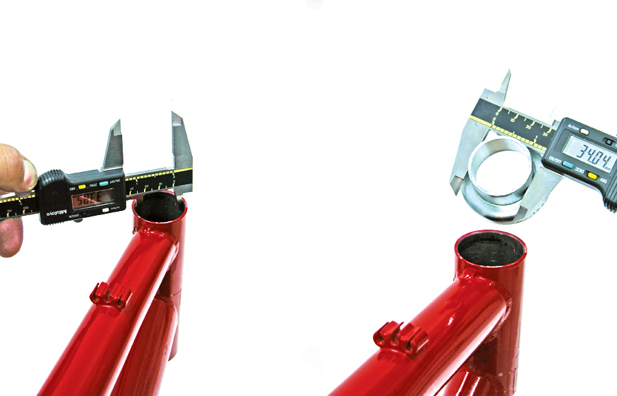
Headset bearing races are held by an interference fit into the head tube. An interference fit occurs when parts are held together by internal and external surfaces forced together. There must be a slight diameter difference between the two pressed surfaces. Typically, the pressed headset race outside diameter should be between 0.1mm and 0.25mm larger than the head tube inside diameter. When the cups are pressed, the head tube will flex and enlarge slightly to allow the cups to press. This tension is what keeps the cups tight in the frame.
Use a caliper to measure the outside diameter of the cups. Next, measure the inside diameter of the head tube in two places, each 90 degrees from the other. Average the two reading. If the head tube more than 0.25mm smaller than the race, it may be reamed using the HTR-1 Headtube Reaming and Facing tool. If the race is between 0.01mm and 0.09mm, a different headset with a larger press race should be used. It is also possible to use a retaining compound such as Loctite® RC609. If the race is equal to or smaller than the head tube, a different race should be used. See discussion of press fit standards below.
The fork bearing race is pressed to the fork crown race seat. The fork race is smaller than the crown race seat. It is the race that expands as it is pressed. Races are commonly made of bearing steel, which tend to be very hard and brittle, and do not expand to the same tolerances as the head tube. The crown race seat should larger then the race by 0.1mm to 0.15. Much more difference may stress and crack the bearing race. When the crown race seat is too large for the fork crown race, it may be milled smaller with the CRC-1 Crown Race Cutter. If the crown race seat is only slightly larger than the race, 0.02 to 0.09mm, use a retaining compound such as Loctite® RC609. If the crown race seat is equal to or even smaller than the race, use a different race. See discussion of press fit standards below.
Pressing Head Tube Cups
This discussion will assume use of the HHP-2 Headset Press and the CRS-1 Crown Race Setter.
- Determine the acceptability of the headset press fit as described above.
- Adjust threaded press plate of HHP-2 until top is flush with end of hex shaft thread
- Remove sliding press plate and install cups onto guides. Guides are used to maintain cup alignment while pressing. Cup guides fit most 1-inch and 1-1/8-inch standard headset cups. Before using cup guide, insert guide into cup. If guide appears to jam or is a tight fit, DO NOT use cup guides for that particular headset cup. Do not use cup guides #530-2 if guides press on any preinstalled cup-bearing unit (ex. Chris King® headsets). For headsets not fitting #530-2 cup guides, simply press using threaded press plate and sliding press plate. Pressure on the outer rim of aluminum head cups may visually scar the cups. If not using the guides, it can help to press one cup at at time.
- Place upper headset cup on top of head tube. Hold one cup guide onto top threaded press plate and lower assembly through top headset cup.
- Install second cup guide onto sliding press plate, and place lower cup onto guide.
- Engage sliding press plate onto hex shaft, and push plate upward until headset cup meets head tube. Release lever. Sliding press plate lever must be engaged in one of seven hex shaft notches. Pull downward on lower press plate to test engagement.
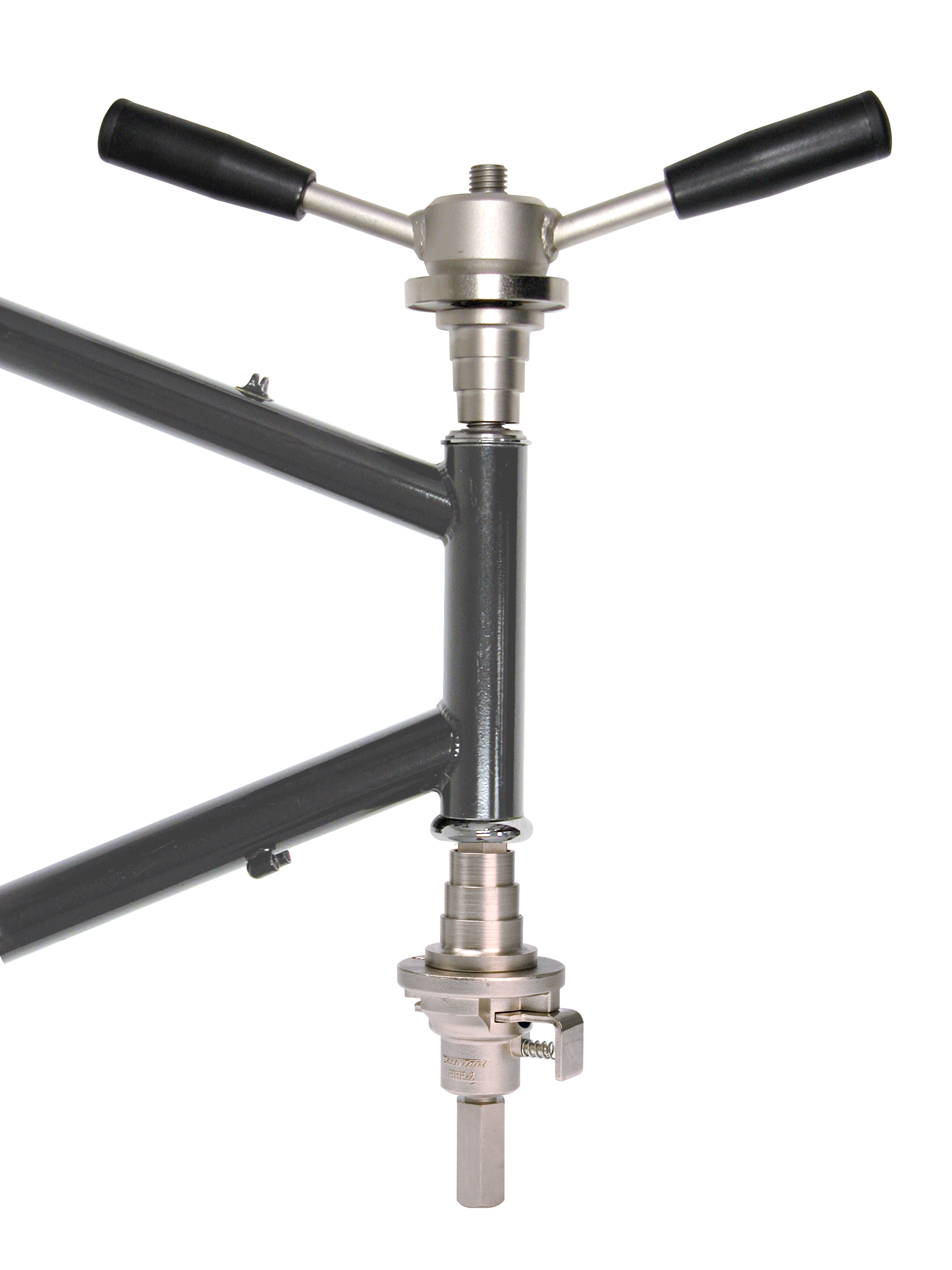
- Turn handle clockwise slowly and inspect alignment of cups as cups enter head tube. Continue and press cups fully into head tube. If threaded press plate has bottomed on threads of hex shaft, turn threaded press plate counter clockwise until it is again flush with top of threads. Re-engage sliding plate to a higher notch, and continue to press cups. NOTE: Never use a “cheater bar” to extend leverage of handles. If cups will not press using handles, other problems are present and should be addressed.
NOTE: If the head cup has preinstalled cartridge bearings, check that any guide will not press directly on the rotating bearing. For these types of cups, press only with the flat plates of the headset press. Press only one cup at a time.
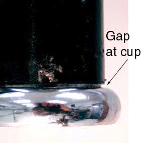
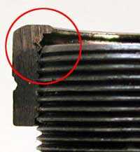
- Inspect for full seating where cups meet frame. A gap indicates incomplete pressing, as seen below.
- Remove HHP-2 from bike. Unthread handle 1 turn, press lever of sliding press plate and remove tool from bike.
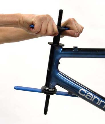
Pressing Fork Crown Race
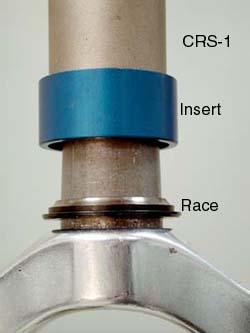
The fork crown race must be pressed to the fork crown. Determine acceptability of press fit as described above. Place race on fork crown and select most compatible CRS-1 insert. Place tool and insert over fork. Use hammer and strike top of tool until race fully seats. The sound will change as it seats. Inspect sides of race for seating.
Headset Assembly
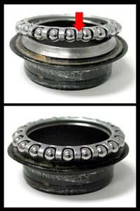
If the headset is using bearing retainers, check the orientation of the retainers before installing. Inspect the metal cage that retains the ball bearings. The cage traps each ball with a hook. Look for the open side of the ball retaining hook. This open side of the cage should face the cone shaped race, not the cup shaped race. If in doubt, install the cage, and place the race inside and turn. If the cage is correct, it will feel smooth. If the cage is upside down, the cage retainer will rub on the race and it will feel different. Reverse the cage and test again.
It is also possible to replace retainer ball bearings with loose bearings. Grease cups to hold bearings, and place balls into cup shaped races. Leave a wide gap the size of two ball bearings, do not attempt to fully fill cup.
- Grease bearing retainers and bearing race cups. Grease also the threads of the steering column.
- Install bearing retainers into cup shaped races.
- Place fork through head tube.
- Thread on adjusting race onto steering column. Continue threading until it contacts bearing and head tube races.
- Install spacers and accessories as appropriate.
- Install locknut.
Headset Bearing Adjustment
Threaded headsets are adjusted using a top locknut and threaded adjusting race. The stem does not have to be removed to adjust the bearings. Generally, the best bearing adjustment is as loose as possible, but without bearing play or knocking. To achieve this, the following procedure will first create play in the adjustment, and then proceed to incrementally tighten the race until play is gone.
- Use a headset wrench to hold lower race (adjustable race).
- Using a large adjustable wrench, turn locknut counter-clockwise to loosen. Lower race is now free to turn.
- By hand, turn lower race clockwise until it contacts ball bearings.
- Turn race back counter-clockwise at least 1/4 turn from this setting. Hold adjustable race with headset wrench and tighten locknut. Tighten locknut fully, see Appendix B for torque. This early setting is intended to have play.
- Check for play by pulling back and forth on fork. A knocking sensation indicates play. Turn the handlebars in different directions while checking for play. There should be play at this early setting. If headset feels tight, loosen adjustment further until play is found. Use care with suspension forks, because the legs may have play in sliders. Grab upper portion of fork.
- If play is present, grab front wheel between knees and hold it in line with top tube. Lower adjustable race will need to be adjusted slightly clockwise. Use a wrench to hold lower race and note orientation of wrench.
- Loosen locknut and move wrench holding adjustable race clockwise 1/32nd of a turn. Front wheel must be straight to gauge adjustment.
- Hold adjustable race from moving and tighten locknut fully. Check again for play, rotating fork and checking different positions.
- If play is present, repeat steps “6” and “7” above until play disappears. Adjustment is finished when there is no play in any position as the fork rotates.
NOTE: Another test of play is to place the bike on the ground and grab the front brake tightly. Press downward on the handlebars and rock the bike forward and back. A knocking sensation may indicate a loose headset. In effect this does the same thing as grabbing and pulling on the fork. However, play in the brake caliper arms may also cause a knocking. Front suspension forks may also have play in the legs, which can cause a knocking. If the adjustment seems very tight after adjustment, there may be other problems in the headset. Bearing surfaces may be worn out, or the ball bearing retainers may be upside down, or a seal may be improperly aligned. If play always seems present no matter the adjustment, the threaded steering column may be too long for the locknut. Add headset washers under the locknut in this case. If this is not the problem, cups may be loose in their press fit in the frame.
Bearing Adjustment and "Feel"
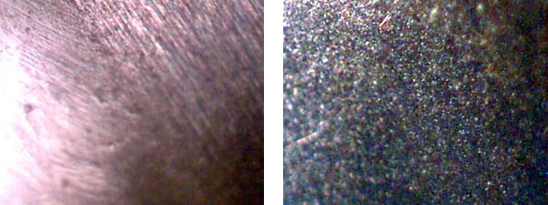
Bearing surfaces are made from hardened steel. The surfaces are cut typically by grinding. Round ball bearings roll on the curved surface of the cup and cone. Even the highest quality bearing surfaces will have slight grinding marks. In the left image below is a high quality cone magnified two hundred times. Notice the parallel marks from the grinding stone. Also note a slight pit from wear. The right hand image is a bearing magnified the same amount. It does show some surface marking, but is generally smoother than the cone or cup. Bearing surface smoothness will vary between manufacturers and between models. Some bearings system will simply feel smoother because they are smoother. This is why it is difficult to adjust by using a subjective feeling of smoothness. Generally, adjust bearings for the loosest setting that has no knocking or play, regardless of this relative smoothness.
Related articles
Threadless Headset Service View Article
Headset Standards View Article
Standardized Headset Identification System View Article
Star Fangled Nut and Expansion Plug Installation View Article
Head Tube Reaming and Facing View Article
Crown Race Removal with the CRP-2 Crown Race Puller View Article
Ceramic Bearings View Article
Fork Steering Column Length and Sizing View Article