TS-RK Rebuild Kit Installation
This article will discuss the installation of the TS-RK rebuild kit into TS-2, TS-2.2, and TS-2.3 Truing Stands.
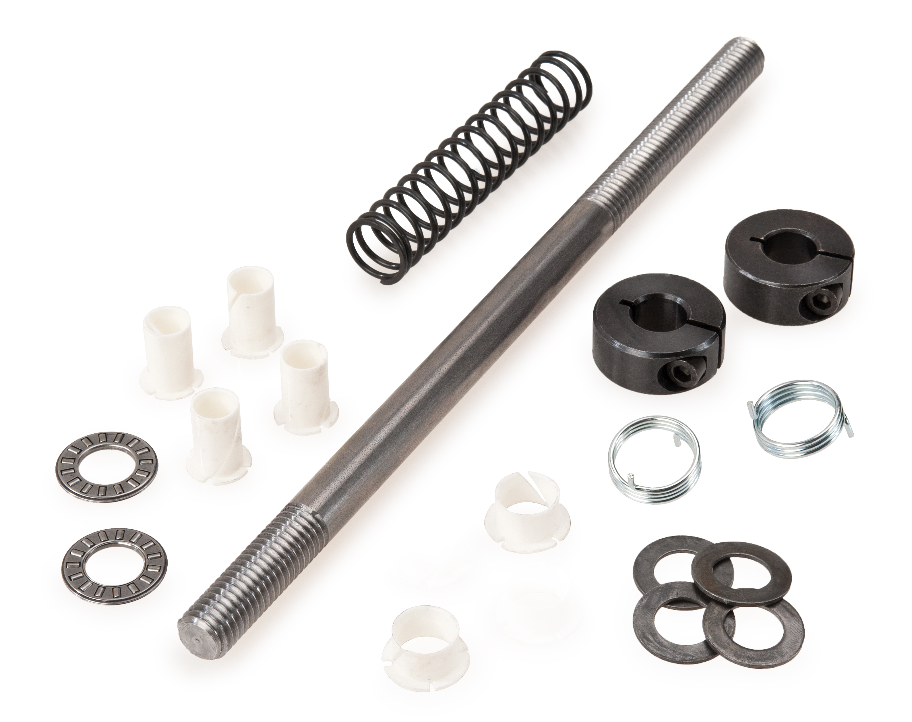
Upright Shaft and Hardware
- Appropriate hex wrenches
- Hammer
- Small adjustable wrench or appropriate combination wrenches
- Small flat-bladed screwdriver
- Grease
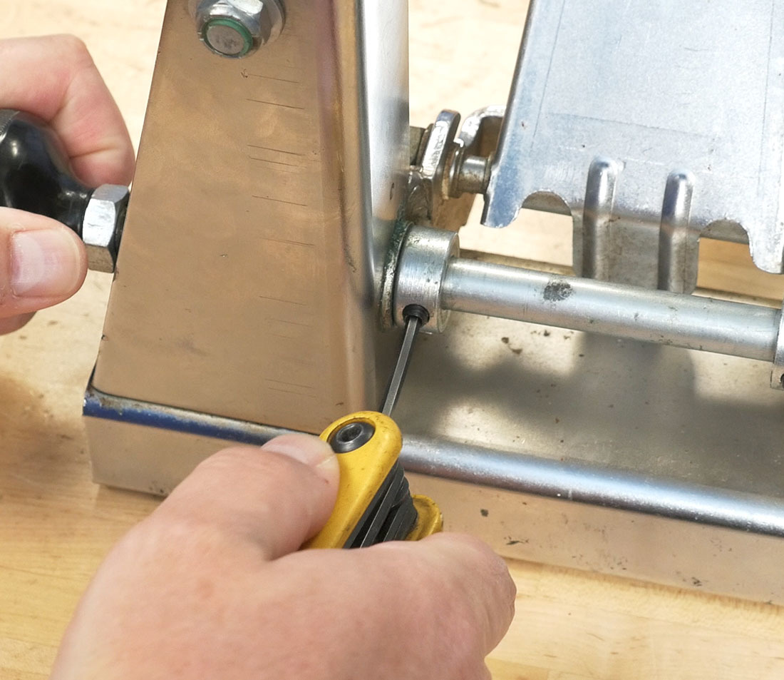
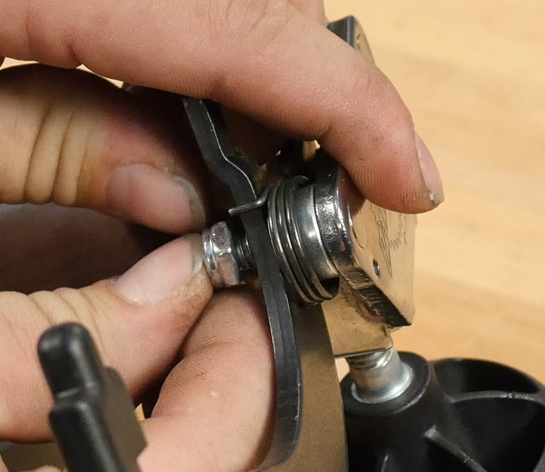
- Loosen the set screws or cap screws located on both of the main shaft adjusting collars (part #209-2). The collars should rotate freely on the main shaft (#211S). Uprights (#201-2) should now move at the top when pushed left or right. On older stands it may be necessary to remove the collar set screws completely and lubricate the holes to free the collars from the main shaft.
Older TS-2 with set screws
Newer TS-2 with cap screws
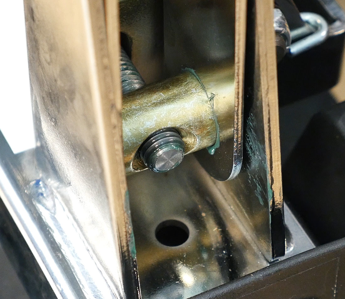
- Remove the right side upright pivot bolt (#225-2) and pull the upright to the right and out of the base (#214-2).
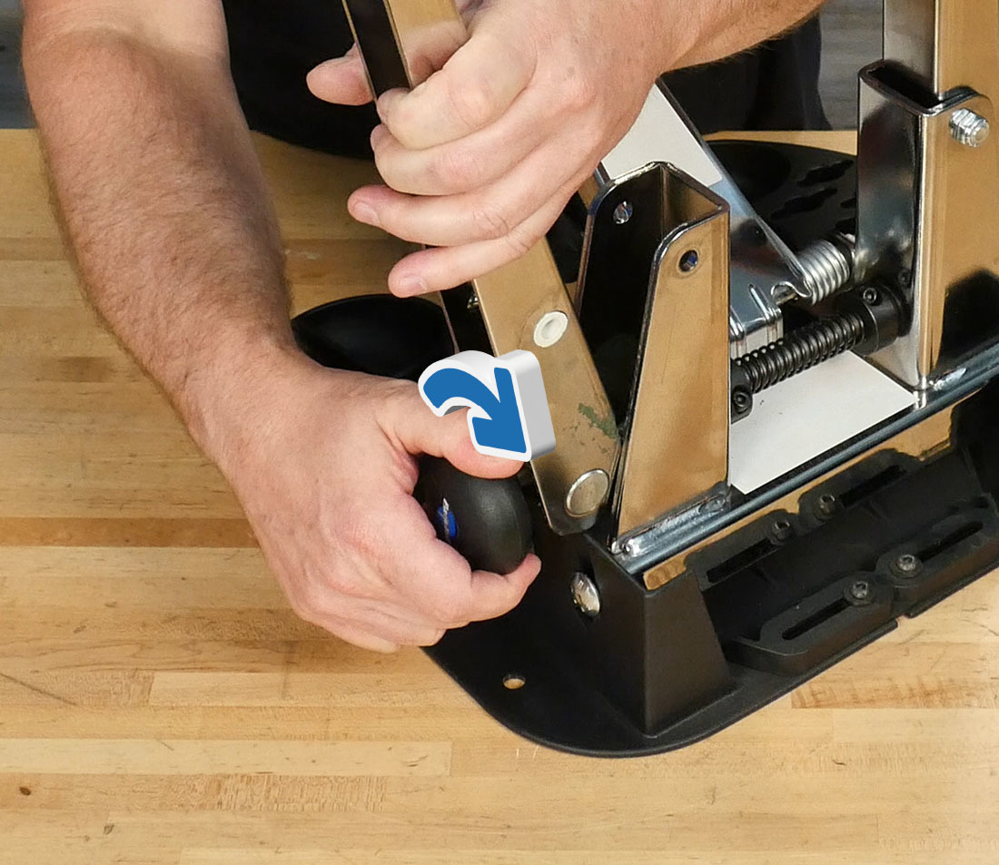
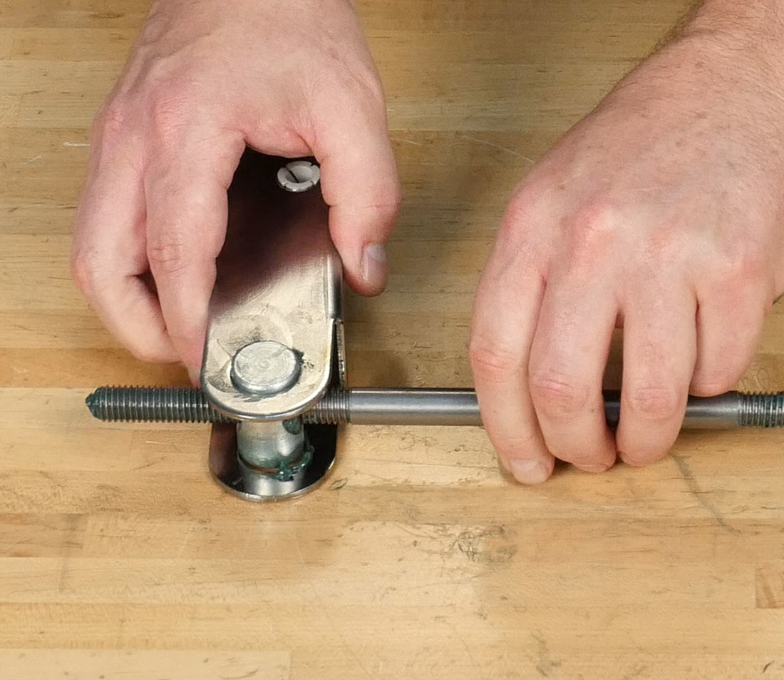
- Turn the knob (#213S) clockwise to disengage the main shaft from the left side threaded pivot-bushing (#204LS).
- Pull the knob (#213S) away from the stand to remove the main shaft and right side upright from the base. Remove the old collars and spring from the shaft as you pull.
- Hold the knob (#213S) as you back off the knob locknut (#212S) using an open-end wrench. Remove both from the main shaft.
- Remove the left side upright pivot bolt and remove the left side upright from the base.
- Remove the old nylon bushings (#232-2) from both sides of both uprights and replace with new bushings.
- Remove the pivot bushings from the uprights, and grease the points of contact between the two parts as well as the outer faces of the pivot bushings.
- NOTE: Use care not to mix up the pivot bushings — the easiest way to avoid this is to grease one set at a time. The left side pivot bushing has left hand threads and has yellow plating. The right side pivot bushing has right hand threads.
- Grease the threads of the new main shaft (#211S). Thread the end with more threads into the pivot bushing on the right side upright.
- NOTE: The main shaft has both left and right hand threads. Right hand threads go to the right side upright and left hand threads go to the left side upright. The right side of the main shaft has more threads than the left side.
- Install the threaded shaft into the right side arm and bushing. Thread the knob locknut onto the right side of the main shaft until 8 threads are exposed (distance of ~16 mm.) Install knob (#213S) and snug the locknut to the knob.
- Guide the main shaft through the right side of the base.
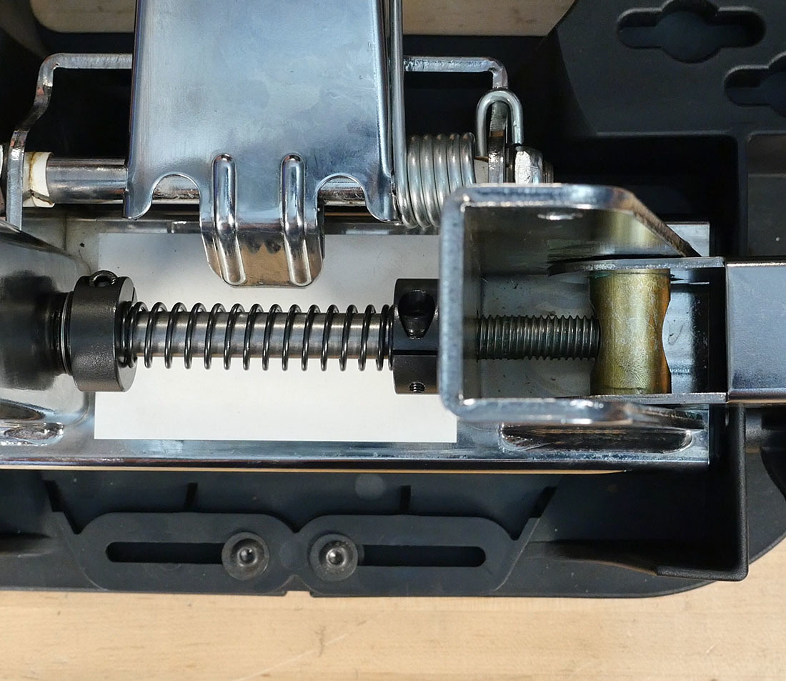
- The following parts, in order, will be installed on the main shaft between the base uprights:
- Bearing Washer (#749-1)
- Needle Bearing (#748-1)
- Bearing Washer (#749-1)
- Main Shaft Adjusting Collar (#209-2)
- Spring (#229)
- Main Shaft Adjusting Collar (#209-2)
- Bearing Washer (#749-1)
- Needle Bearing (#748-1)
- Bearing Washer (#749-1)
- Bearing Washer (#749-1)
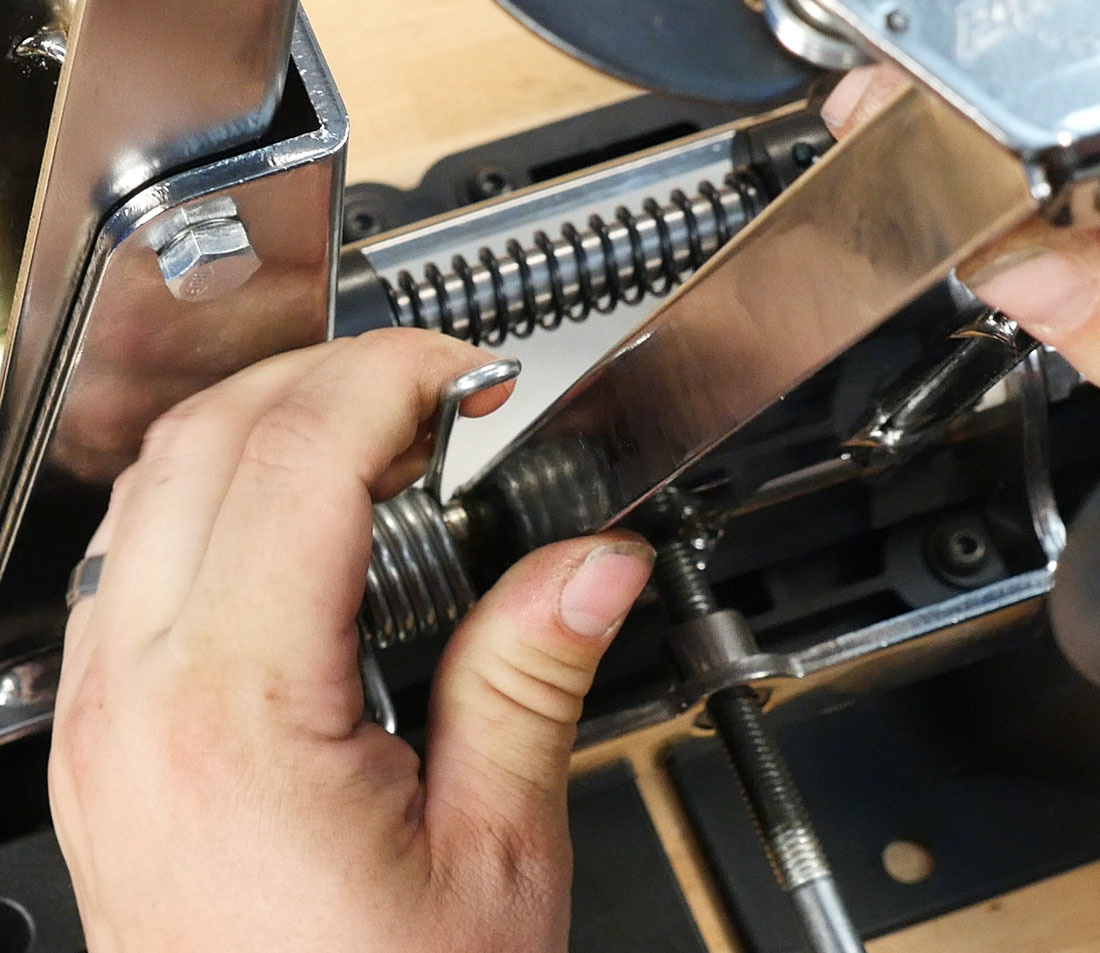
NOTE: It is necessary to compress the spring to install the left hand set of collar, washers, and bearing.
- Once all parts are installed, insert the main shaft through the hole in the left side of the base.
- Install the right side upright fully into the base.
- Line up the left upright and pivot bushing against the end of the main shaft. Maintain pressure against the main shaft and rotate the knob counterclockwise to begin threading the shaft into the pivot bushing. If more than one rotation of the knob is required to engage the main shaft into the bushings, unthread the main shaft and start threading again.
- Continue to thread the knob counterclockwise until the main shaft just begins to protrude out of the left side pivot bushing.
- Install the right side upright and pivot bolt into the base. Tighten bolt fully.
- Grab both uprights and move them side-to-side until they appear approximately symmetrical. Fine-tuning will come later.
Caliper Arm Bushings
- Loosen the caliper adjusting knob (#217S) until the caliper arm (#207-2) is nearly vertical in order to relax the tension in the spring (#206S).
- Unhook the spring (#206-2) from the caliper arm.
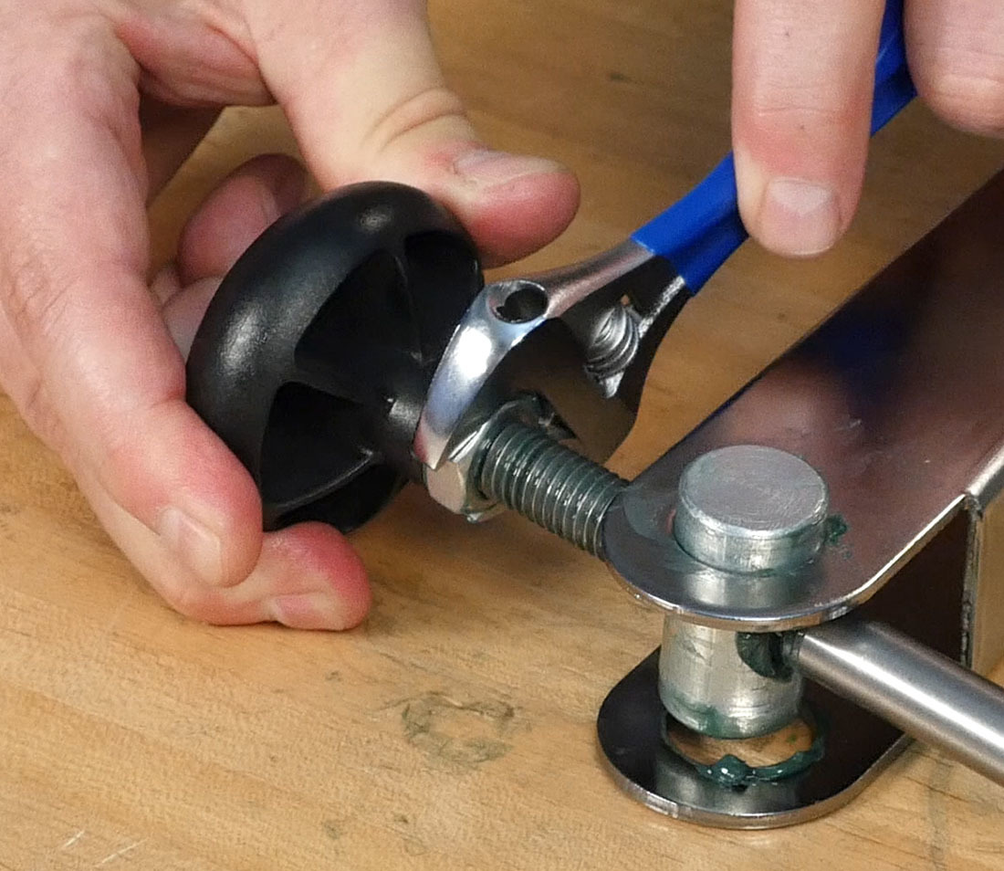
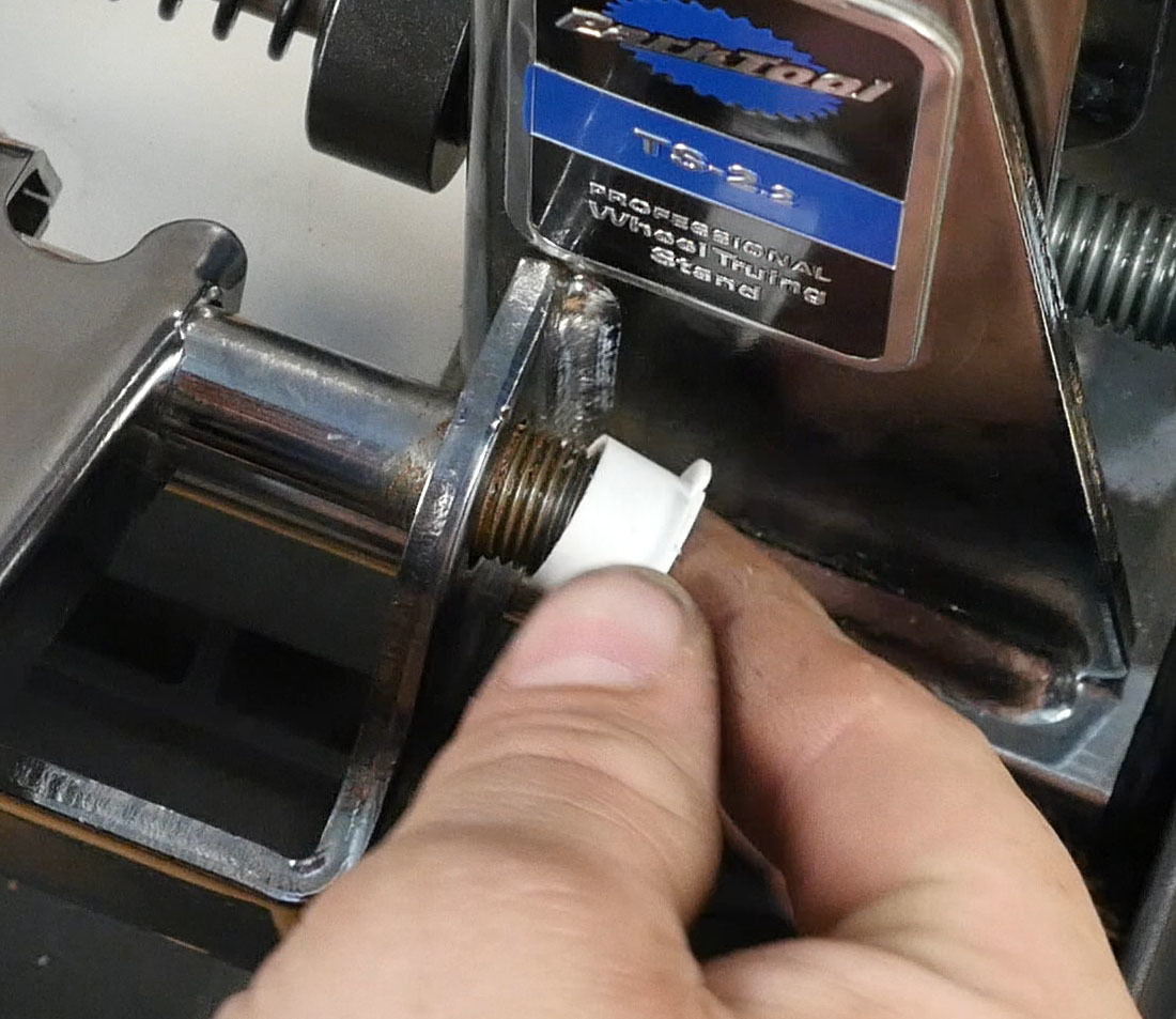
- Remove the right side caliper locknut (#233-2), washer (#234-2), and bushing (#235-2).
- Install the new bushing (#235-2).
- Reinstall the right side washer and nut.
- Repeat the process on the left side — remove the caliper locknut and washer, replace the bushing, and reinstall.
- Check the adjustment of the caliper arm. Locknuts should be as snug as possible but still allow the caliper arm to freely move up and down.
- Raise the caliper arm again to a vertical position and reinstall the spring.
- Lower the caliper arm to working height of rim using the caliper adjusting knob (#217S).
Caliper Springs
NOTE: Test the caliper springs by moving the caliper outward and releasing. If spring is not fatigued, save replacement springs #222-SR and #222-SL for future use. Note that right side spring #222-SR coils counter-clockwise, and left side spring #222-SL coils clockwise.
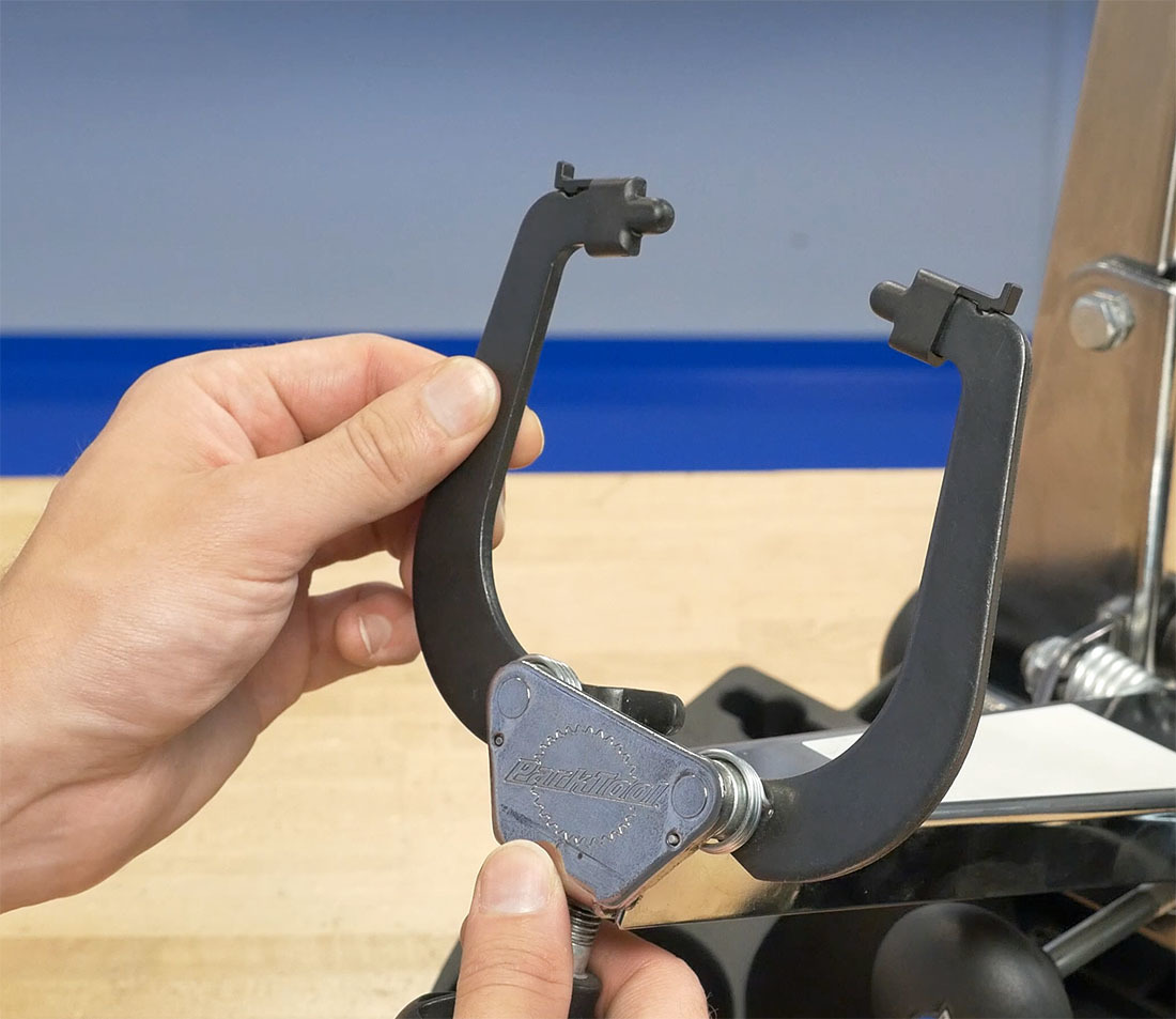
- Loosen the caliper adjusting knob (#224S) until the shaft is almost fully unthreaded from the caliper arm.
- Remove the left side caliper locknut (#226-2), caliper, caliper spacer (#228-2) and spring (#222-SL).
- Install the spacer, new spring, caliper and locknut onto the left stud of the caliper arm. Make sure the spring is engaged into the hole on the caliper arm. Tighten the locknut just enough to retain everything.
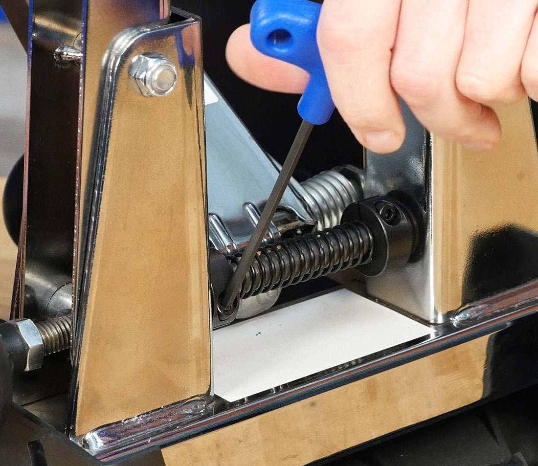
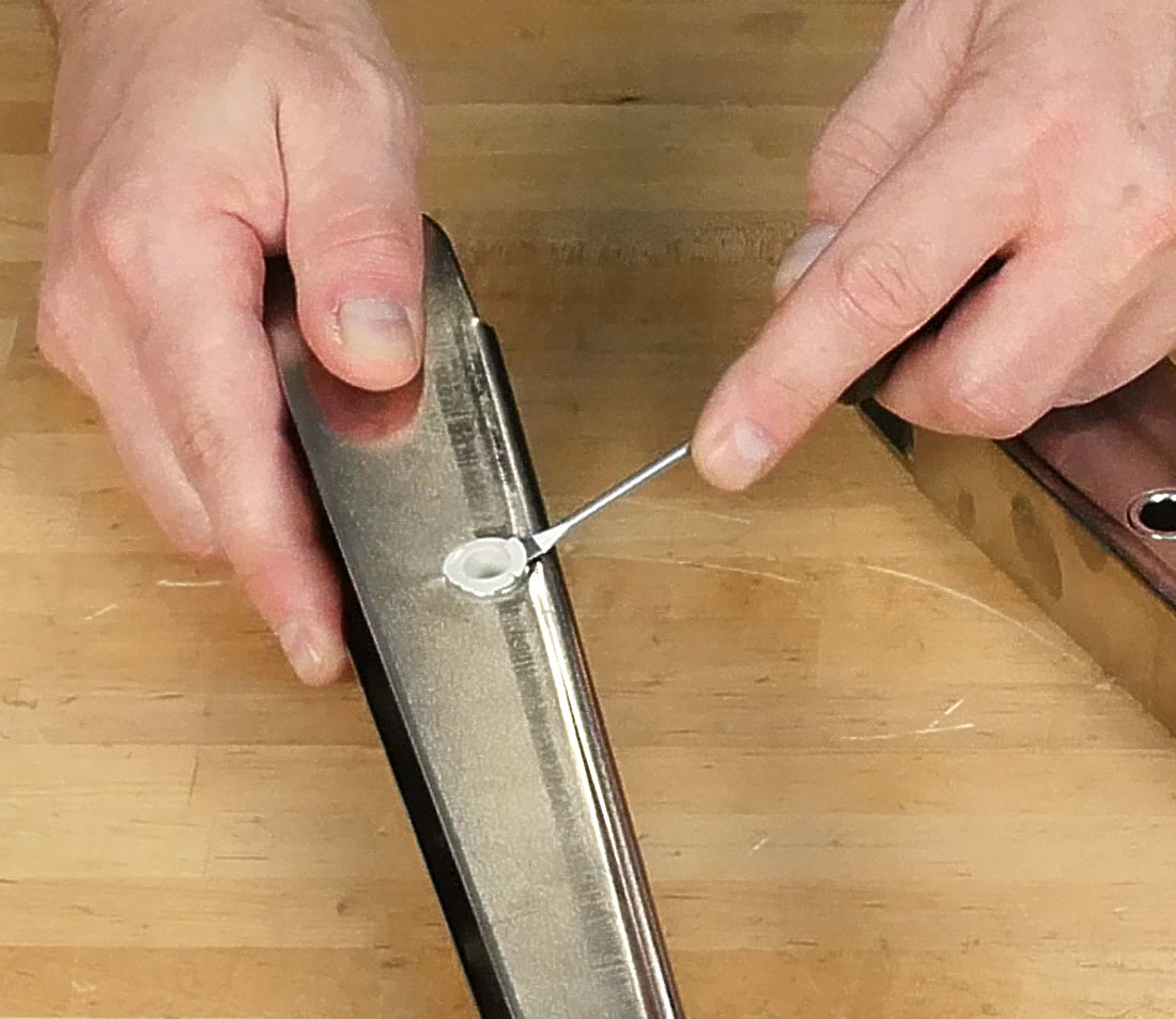
- Engage the end of the spring into the hole of the caliper. The easiest way to do this is by using a small flat-bladed screwdriver to guide the spring into place.
- Repeat steps 2–4 on the right side caliper, using the new right side spring (#222-SR).
- Check the adjustment of the caliper locknuts. Snug the locknuts but do not over tighten. Pull back slightly on each caliper and release. If the caliper does not freely return, back off the locknut ¼ turn and try again.
- Tighten the caliper adjusting knob (#224S) until the caliper opens up to working position.
Final Steps/Calibration
An important final step is to re-center each component of the truing stand. Full instructions can be found here: How to Center Park Tool Truing Stands.
While the TS-2, TS-2.2, and TS-2.3 are designed to provide automatic dishing of the wheel, imperfections in the shape or condition of the axle or locknuts can affect the dish reading, as the imperfection is magnified significantly by the distance from the hub to the rim, where the actual reading is taken. Because of this, for precision work, a dishing tool such as the Park Tool WAG-4 or WAG-5 should be used to verify final adjustments — see Wheel Dishing (Centering) for the full process.
Related articles
How to Center Park Tool Truing Stands View Article