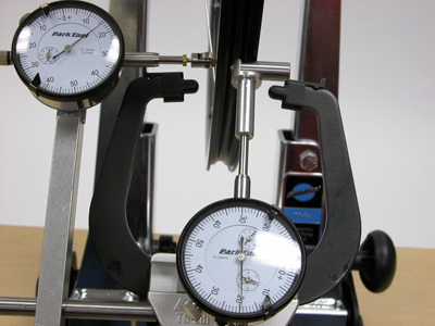
TS-2Di Dial Indicator Use in Wheel Truing
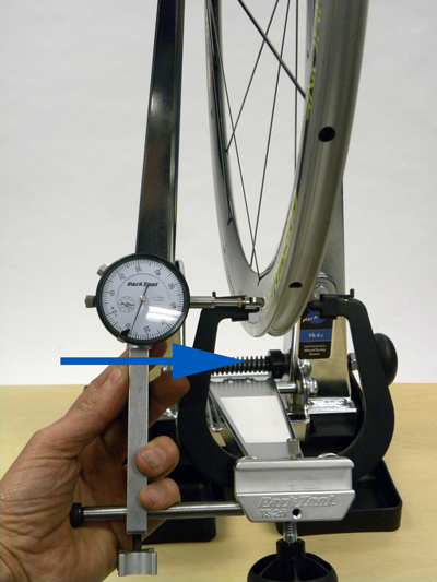
The TS-2Di Dial Indicator Set is designed to fit any Park Tool TS-2, TS-2.2, or TS-2.3 Truing Stand (figure 1). The TS-2Di provides a quantitative measurement of a wheel’s lateral (side to side) and radial (up and down) trueness or run out. By setting standards for lateral and radial true, and having all mechanics true to these standards, a service department can save time, be more productive, and produce consistent results for all wheels.
Assembly / Installation
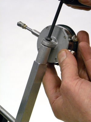
- Install mounting bracket assembly onto caliper faceplate of truing stand . The mounting bracket has two setscrews on either side (figure 2). These screws should be threaded in to expose approximately 3-4mm of thread. These thread will catch the backside of the TS-2, TS-2.2, or TS-2.3 caliper face plate (figure 3).
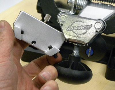
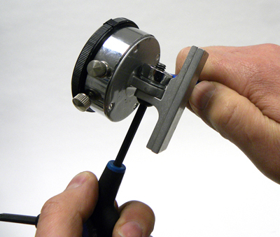
- Hold mounting plate and secure setscrew on face of mounting plate using a 3mm hex wrench. The setscrew pushes against TS-2 face place and holds mounting bracket in place (figure 4).
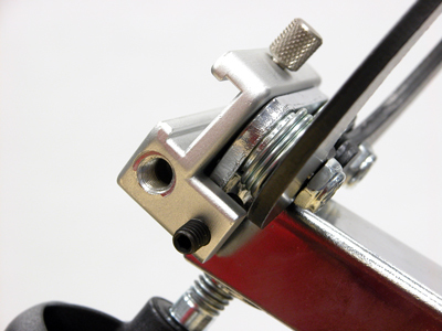
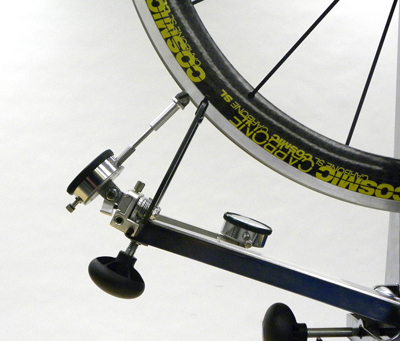
- Slide lateral dial bracket onto shoulder bolt. Install shoulder bolt into either side of the mounting bracket as preferred. Secure shoulder bolt using a 3/16″ fractional hex wrench (figure 5). As a substitute use the T30 size torx-type wrench.

- Install lateral dial indicator using bolt, washer and dial bracket extension (figure 6). Align shaft of the dial indicator parallel with shoulder bolt. Use knob at end of lateral bracket to position and hold lateral dial indicator.
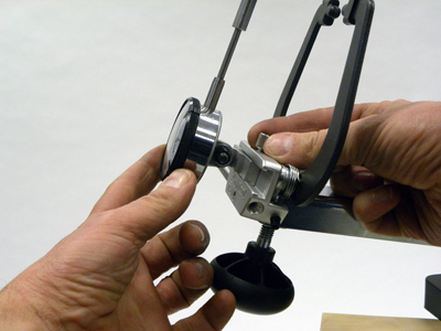
- Install radial dial to bracket using bolt, washer and nut (figure 7).
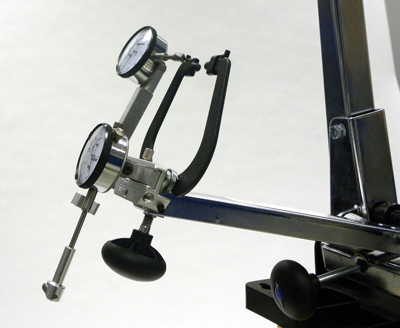
- Install radial dial assembly by sliding radial dial bracket into front of mounting bracket (figure 8). Tighten knurled knob to secure.
NOTE: When not in use, the radial dial assembly should be stored off the truing stand when not in use to prevent damage and contamination. When truing a wheel with tire in place, it is common for dirt to fall on to the caliper plate area. Storing the dial assembly on the stand would invite contamination. Another option is to store the radial dial assembly upside down (figure 9).
Using the Dial Indicators
The dial indicators are intended to check and quantify the run out or movement of the rim. Using the dials for truing and correcting can be difficult because the dials will spin quickly when a very out of true or round wheel is spun in the truing stand.
- Inspect surface of rim sidewall for scarring, burrs or dents, which may interfere with contact of dial indicator tip. Remove surface imperfections if possible. It is possible the rim seam or joint may show anomolies as the rolls passes over this area.
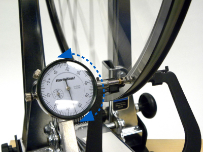
- Loosen knob and slide lateral dial bracket on shoulder bolt until roller tip contacts sidewall of rim (figure 10). Continue sliding lateral bracket on shoulder bolt until plunger is depressed 5mm–10mm and tighten knob to lock bracket position. The dial indicator may be placed in front or behind caliper fingers as desired (figure 11).
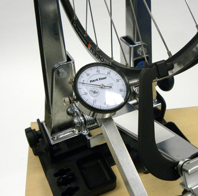
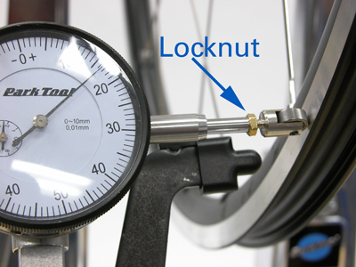
- Roller should be aligned to it is approximately tangent (parallel) to the rim. Loosen lock nut with 6mm open end wrench or small adjustable wrench. Align roller tip with radius of rim and secure nut (figure 12).
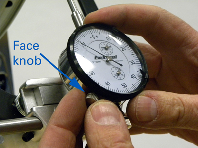
- Each dial indicator in the TS-2Di reads in metric increments and uses a “balanced face”, meaning readings progress both clockwise and counterclockwise from “0” (figure 13). The dial face may be rotate to set any point as “zero”. Loosen the dial face locking knob on the side of either dial (figure 14). Each line on the dial face represents .01mm. One complete revolution of the dial needle represents 1mm. There is a smaller rotation dial inside the dial face, which is a revolution counter for the dial face needle. Each dial indicator has two range indicating clips, which can be used to preset an acceptable range of run-out as seen on the dial face.
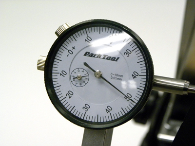
- For a quick and simple reference, note position of dial on dial face. Slowly rotate rim and note the two extrememe swings of the dial. For example, if the dial swings less then a complete rotation, the rim has a run out less then 1mm. If the dial swings less the have the dial face, the rim has a run out less the 0.5mm (figure 15). A dial swing 1/4 of the face has a run out of 0.25mm.
- For a more exact run out reading, loosen the dial face locking knob and rotate the knurled outer ring either direction until “0” aligns with dial needle. Rotate rim slowly for one complete revolution and note run-out as indicated by dial needle on dial face. Run-out is the total swing of the dial needle on either side of “0”. For example, if the needle is aligned with “0” on the dial face at an arbitrary point, and then moves clockwise to 0.3mm at some point as the wheel is rotated, and then counterclockwise to 0.4mm at some other point, the run-out total is 0.7mm.
- If run-out is within desired standard, the wheel is adequately trued. If not, adjust spokes as needed to true wheel to desired standard.
Measuring Radial Run-Out
- Inspect edge of rim sidewalls (tire must be removed) for scarring, burrs or dents, which may interfere with contact of radial dial bar. Remove surface imperfections if possible.
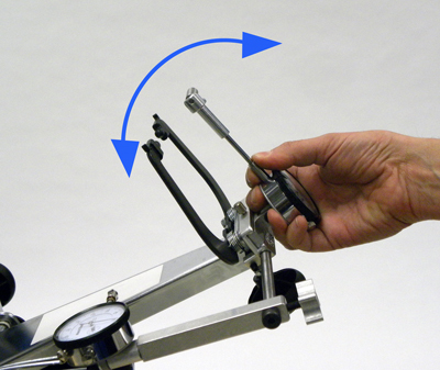
- Adjust caliper below rim with enough room to mount radial caliper assembly. Tilt angle of dial on radial dial until dial shafts point approximately at center of hub (figure 16).
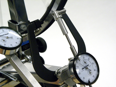
- Adjust dial laterally so dial bar is under one flage (figure 17). NOTE: Dial bar does not need to contact both rim flanges.
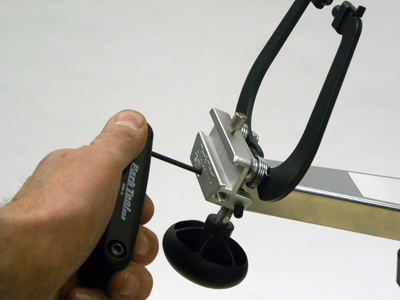
- Loosen caliper arm to raise dial assembly toward rim and depress dial plunger 5-10mm (figure 18).
- Rotate rim slowly for one complete revolution and note run-out as indicated by dial needle on dial face (figure 19). If run-out is within desired standard, the wheel is adequately trued. If not, adjust tension of spokes as needed to true wheel to desired standard.

Related articles
Wheel Truing (Lateral & Radial) View Article