RockShox® Pike® Suspension Fork Service
This article will review the service of the RockShox® Pike® suspension fork.
Getting Started
- Repair Stand
- MG-2 Nitrile Mechanic's Gloves
- Hex Wrenches
- HMR-4 Shop Hammer
- Torque wrench or torque driver with appropriate bits: Torque Tools and Bits
- Rubbing alcohol
- Soft cloths
Suspension systems are sophisticated technology and service often requires proprietary tools and specialized knowledge. A professional mechanic trained in suspension service should perform internal tuning and detailed service. However, some model forks allow for certain services to be performed by the home mechanic. The emphasis in this article will be on what service the consumer should perform to the RockShox® Pike® fork. The procedure is the same for all RockShox® “coil fork” systems.
Begin by mounting the bike in a repair stand and removing the front wheel. Remove the disc caliper and hydraulic tubing from front fork. Grab both legs and pull forward and back to check for knocking or play. If play is felt, test further to isolate source. Knocking from the headset can be adjusted. However, if the upper tubes are moving and knocking inside the lower legs, the internal bushings are worn. The fork should then be serviced by a professional mechanic.
Prepare a box to catch the spent fluid from the fork. You may use a plastic liner in a cardboard box. It is also recommended to wear protective gloves such as the MG-2, and use eye protection. Shock fluids are mostly mineral oils or spirits. Work over this box when removing the legs.
Shock Disassembly
Inspect under the fork leg ends for an adjustment knob. Pull the adjusting knob from fork (Figure 1) Note also any fluid drips on either bolt which may be the result of a leak. A leak indicates the need for new “crush washers” on the leg bolts.
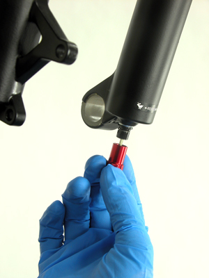
Figure 1. Remove adjusting knob
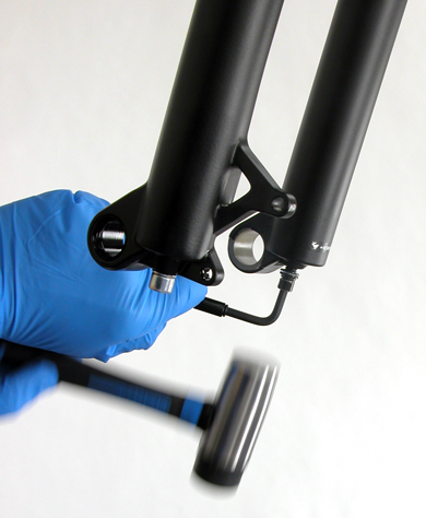
Figure 2. Use a hammer to drive bolt back into legs
Use a 5mm hex key to loosen each bolt 3–4 turns. Expect fluid to begin dripping at this time, so work over the box or trash can. The lower leg bolts secure the damper shafts to the lower legs. The shafts must be freed from the lower legs before they can be removed. Place a 5mm hex key in the bolt and use a hammer to tap on the wrench to drive the bolt inward (Figure 2). This frees the inner struts from the lower legs.
Loose each bolt fully and remove (Figure 3). Note that one bolt is hollow to accept the hex wrench fitted into the adjusting cap.
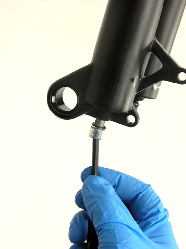
Figure 3. Remove bolt bolts
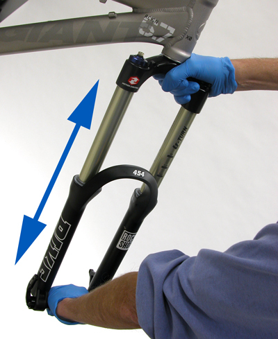
Figure 4. Pull lower legs from upper tubes
Pull downward with force on the lower legs and remove from upper tubes. It can be useful to reinstall the axle to act as a handle when pulling (Figure 4). Note: Never strike the forks or arch between the legs to disassemble.
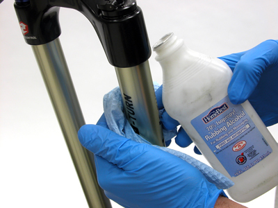
Set the legs in the box and allow all fluid to drain. Use a clean cotton rag or lint-less towels to clean outside of upper tubes using isopropyl alcohol (Figure 5). Inspect upper tubes for any scratches. Minor scratches or blemishes may not be an issue. However knicks and deep scratches may result in leaks.
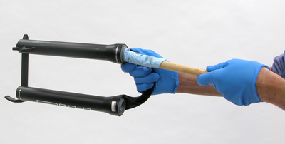
Using isopropyl alcohol, lint-less rags, and a dowel or similar object clean inside the lower legs (Figure 6). It is not necessary that the leg interiors be completely clean of all fluids. However, dirt should be removed.
Shock Assembly
The two lower leg bolts use a “crush washer” to form a seal (Figure 7). With repeated removal and installation, these washers will wear out and become deformed. When this occurs it will eventually allow fluid to leak. Typically these washers can be reused four to five times before they should be replaced.
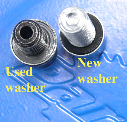
Figure 7. Replace crush washer if a leak develops at the bolt
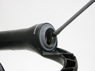
Figure 8. Lubricate any newly installed seals
For normal cleaning service, it is not necessary to replace the upper seals, wipers, or foam rings in the lower legs. However, if any of these were replaced, lubricate them with several drops of suspension fluid (Figure 8). Another option is to grease the inside of the seal using a bearing grease such as the PPL-1.
Engage both lower legs on upper tubes simultaneously (Figure 9). Use care not to pinch or deform the seals when the legs are engaged (Figure 10). Remove the lower legs and start over if seals are not properly aligning.
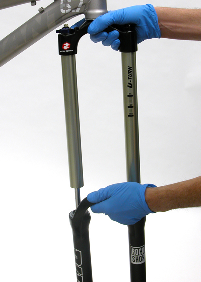
Figure 9. Install lower legs onto upper tubes
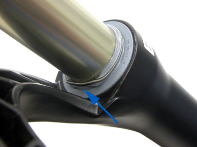
Figure 10. This seal was deformed by poor engagement
Pull lower legs fully onto upper tubes, and then push down approximately 1″ to allow installation of shock fluid.
Rotate the bike in the stand so the fork legs are pointing upward about 45-degrees. Each leg will receive RockShox® suspension fluid (15W) to provide lubrication. Use a syringe if available to inject 15ml (1 tablespoon) fluid into each bolt hole. It is also possible to use plastic sheet stock rolled into a cone shape to act as a funnel (Figure 11). Use tape on outside of funnel to hold its shape.
The amount of suspension fluid installed in the legs will vary with the diameter of the upper tubes.
- 28mm upper tubes: 10ml (2 teaspoons)
- 32 and 35mm upper tubes: 15ml (1 tablespoon)
- 40mm upper tubes: 20 ml (1 tablespoon plus 1 teaspoon)
NOTE: One ml (milliliter) is equal to one cc (cubic centimeter)
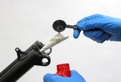
Figure 11. Use a small funnel and pour in leg bolt holes 15ml (1 tablespoon) suspension fluid
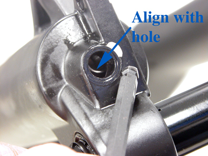
Figure 12. Push inner shaft to align with hole before installing bolt
With fork still pointing upward, push lower legs fully onto upper tubes. Inspect inside each fork bolt hole for the damping shaft. Use a small hex wrench to push the inner shaft until it aligns adequately with the bolt hole (Figure 12).
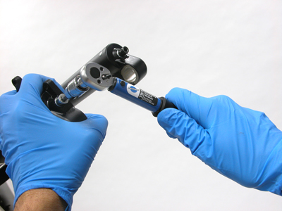
Install lower leg bolts into the corresponding legs. The hollow bolt install on the left side. Fully thread the bolts into their holes and secure each to 6.8 Nm (60 in-lbs) using when possible a torque wrench such as the TW-5.2 (Figure 13).
Rotate the bike to a normal orientation. Clean any excess fluid from the fork exterior with isopropyl alcohol. Install the front wheel and brake system.
After use, check the lower legs at the mounting bolts. If fluid appears it is an indication that the crush washers should be replaced.
Related articles
RockShox® Rear Shock Service—Monarch 4.2 View Article