Three-Piece Crank Removal and Installation
This article will demonstrate removal and installation of three-piece cranks. It covers square tapered spindles as well as splined style such as ISIS Drive and Octalink.
Getting Started
- Appropriate wrench to remove crank bolt/nut:
- CCW-5 Crank Wrench
- Hex wrench
- MW-SET.2 Combination Wrenches
- PAW-12 Adjustable Wrench
- Crank puller:
- Torque wrench
- Thread preparation:
- Rags
Cranks connect the pedals to the bottom bracket spindle and are pressed tightly to the bottom bracket spindle which are held in place by force from well-torqued crank bolts or nuts. Cranks must be removed from the spindle to service the bottom bracket bearings or to replace the chainrings.
Crank pullers are used for the removal of basic three-piece crank types: square-type spindle arms, and splined-type spindle arms.
Square tapered spindles are made with a slight slope or taper. This shape creates a wedge as it is driven into the square hole of the crank. Adequate torque from the crank bolt is typically enough to keep arms from creaking. If a crank creaks even at full torque, remove and grease the pressed surfaces.
Cranks used with a loose bolt will result in movement and wear between steel spindle and the sqaure hole the crank. When the spindle end is no longer recessed inside the hole, the crank bolt can not apply pressure to hold the arm tight on the spindle. A worn crank will need to be replaced.
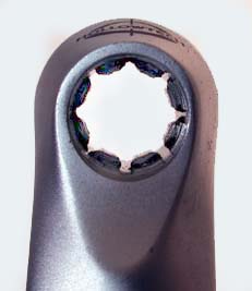
Octalink standard from Shimano®
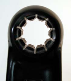
ISIS Drive standard
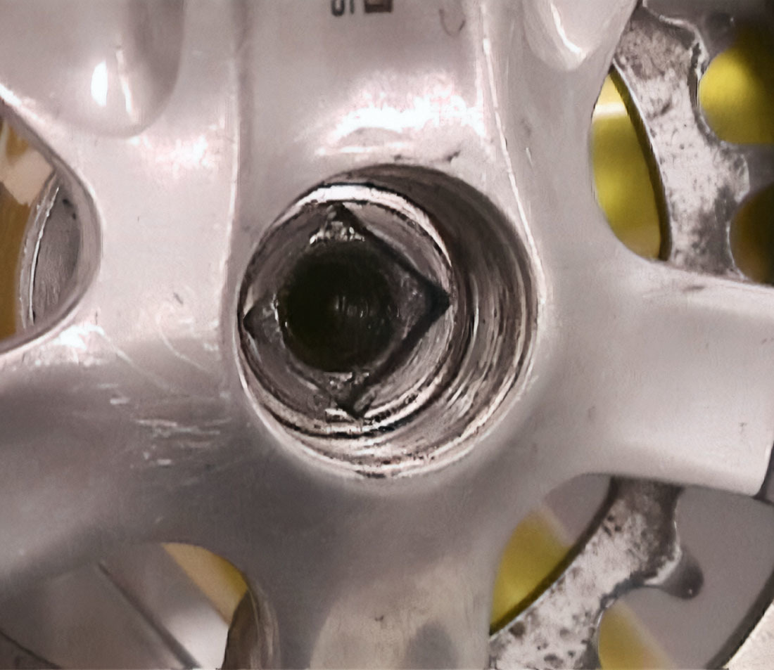
Certain road and MTB models of Shimano® cranks uses an 8-spline design called Octalink®. The oversized pipe billet splined spindles are round at the ends rather than square shaped. A series of internal raised splines in the crank are mated to recessed external splines on the spindle. The cranks are held tightly to the spindle by tension from the crank bolt.
Another standard is the ISIS Drive® (International Spline Interface Standard). The ISIS Drive® system uses ten splines of a different shape from Shimano®. The ISIS Drive® and Octalink® systems do not interchange for either cranks or spindles.
Cranks that are sold with a “one-key release” or “self extracting” system do not require a crank puller. For details on how to service these cranks, see our article on Crank Removal and Installation: Self-Extracting.
Crank Removal
- Shift the chain to the largest chainring. This helps protect your hands from the chainring teeth.
- Remove the crank bolt or nut by turning counterclockwise.
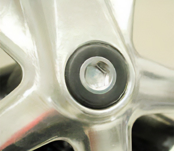
- If no bolt is visible, remove dust caps. Some caps pry out and some thread out.
Dust cap hiding bolt beneath
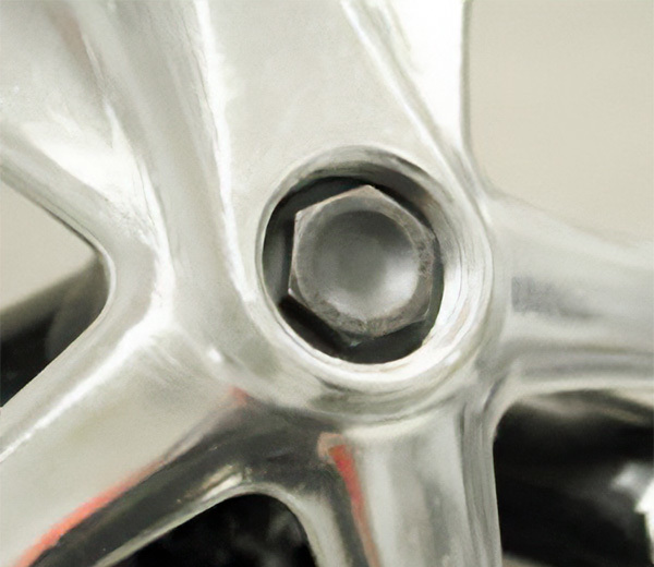
Hex head bolt
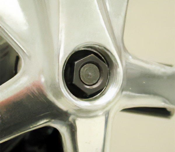
Socket head bolt
Crank nut on threaded spindle stud
- Remove any washers inside the crank that were below the bolt/nut.
- Inspect the crank bolt and select the appropriate tool:
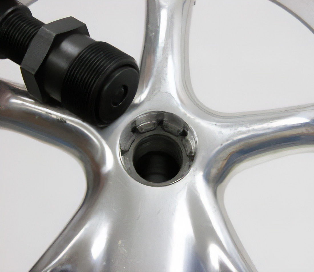
- Turn the threaded coupler of the crank puller until it sits recessed in the hex fitting of the tool, taking care not to cross thread. This permits full engagement of the 22 mm thread into the arm.
- Thread the spindle driver of the puller into the arm. The 22mm thread fitting must be fully threaded into the arm before pulling the arm.
- If the spindle driver is not completely threaded and engaged into the crank arm, the threads of the arm or nut may be damaged.
- Turn the spindle driver clockwise. When the driver meets the spindle, resistance will be felt. Continue threading the driver into the puller until the crank is removed.
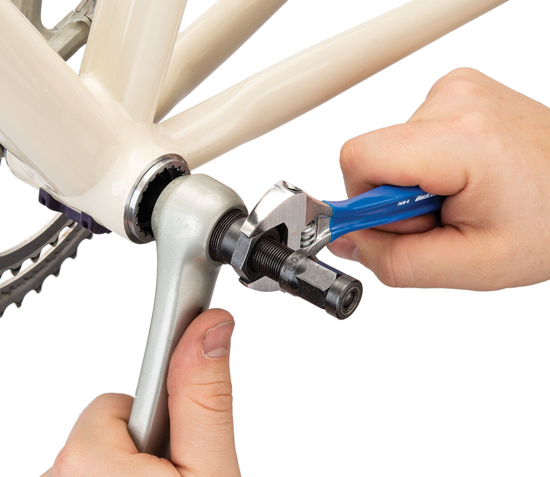
Secure puller nut into crank
Turn handle to pull arm from spindle
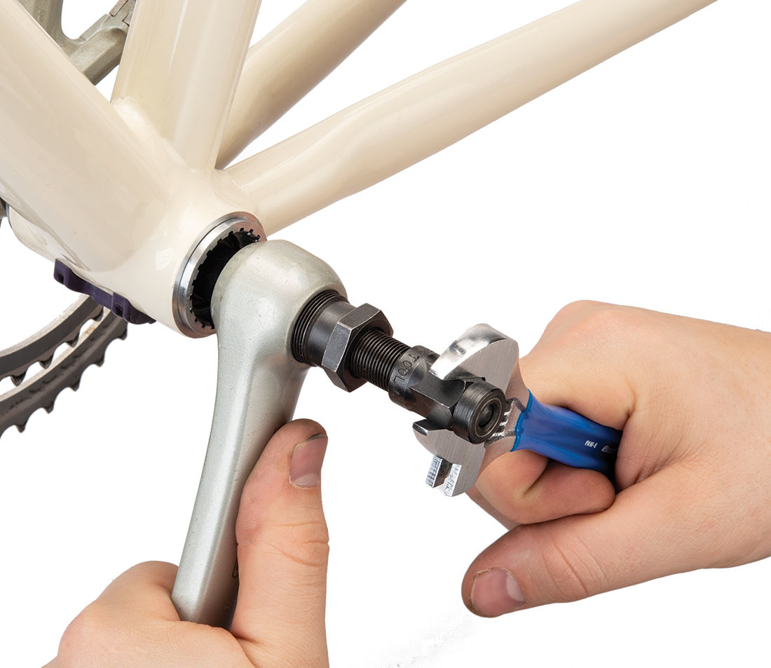
- Unthread the crank puller tool from the crank.
- Use care not to skin your knuckles when removing the tool.
- Repeat the process on the other side.
Crank Installation
- Apply grease or anti-seize compound under the head and on the threads of the bolts/nuts.
- For square tapered spindles, leave the spindle clean of grease. Apply grease or anti-seize compound onto the splines of spline type spindles.
- Rotate the pipe billet spindle so one spline aligns to top dead center, at the 12:00 position.
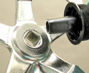
Square hole and square spindle end
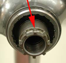
Keep the raised spline aligned at the top 12:00 position
- Position the right crankarm onto the spindle so the arm points straight down at the 6:00 position.
- Install the right crank onto the right side of the spindle. Thread the bolt into the spindle. Self-extracting models: align the tooth and groove of the spindle and crank when installing.
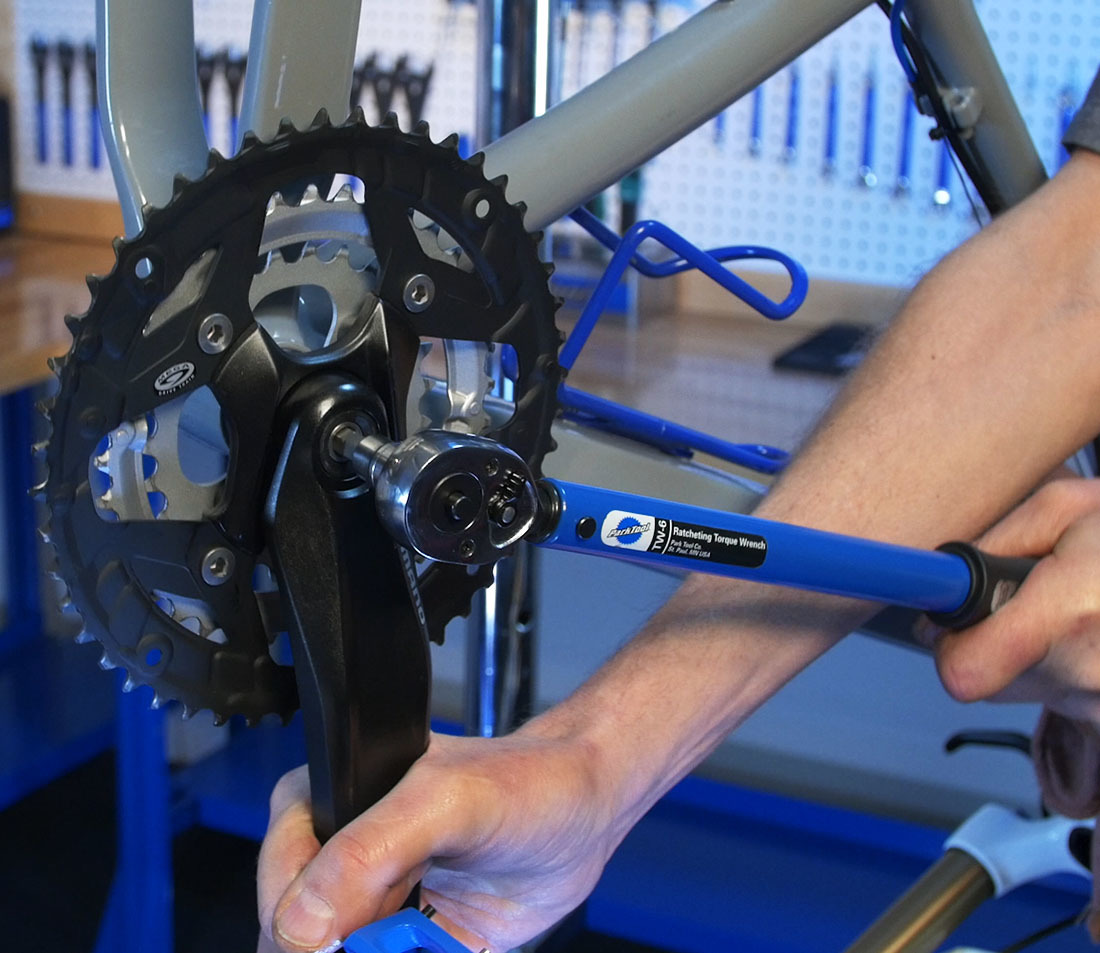
- Tighten the crank bolt fully to manufacturer’s specifications.
- The bolt may need 34 Nm to 50 Nm (300 to 450 inch-pounds) depending upon the brand. Whenever possible, use a torque wrench for this installation.
- Align the left arm so it points directly opposite the right arm. Self-extracting models: align the tooth and groove of spindle and crank when installing. Thread the bolt into the spindle and tighten the bolt fully.
- Grease the threads of the dust cap (if any), and install snugly.
- Repeat the process on other side.
Related articles
Crank Removal and Installation: Self-Extracting View Article
Crank Removal and Installation: Two-Piece Compression Slotted View Article