Center Pull Brake Service
This article will discuss brake mounting and adjustment for the center pull rim brakes.
Getting Started
Center pull brakes tend to be found now on vintage road bikes. Each arm will have a separate pivot locate above the rim. Arms are pulled from the middle with a straddle wire carrier, hence the name “center pull.”
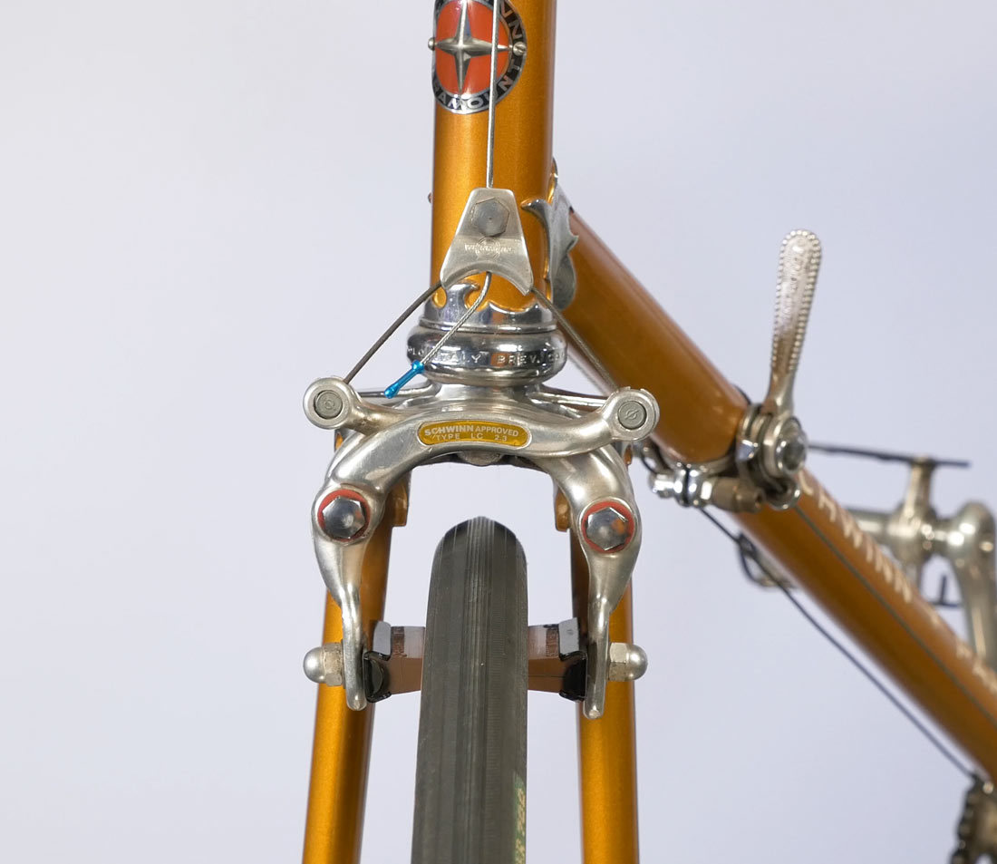
The brake pads move upward on an arc as they approach the rim. Because of this brake pads should be set to the the lower edge of the braking surfaces so as the pads thin with wear, they will not climb up above the rim into the tire.
Caliper Installation
The center pull is mounted to the frame with a mounting bolt. There will be a concave washer system for the convex surfaces of the frame or rear stays. Install the brake through the mounting hole and install the nut, tightening to approximately 6–7 Newton meters.
When installing a center pull it is important to hold the brake centered to the rim. An off-center caliper will result in misaligned pad height.
Pad Adjustment
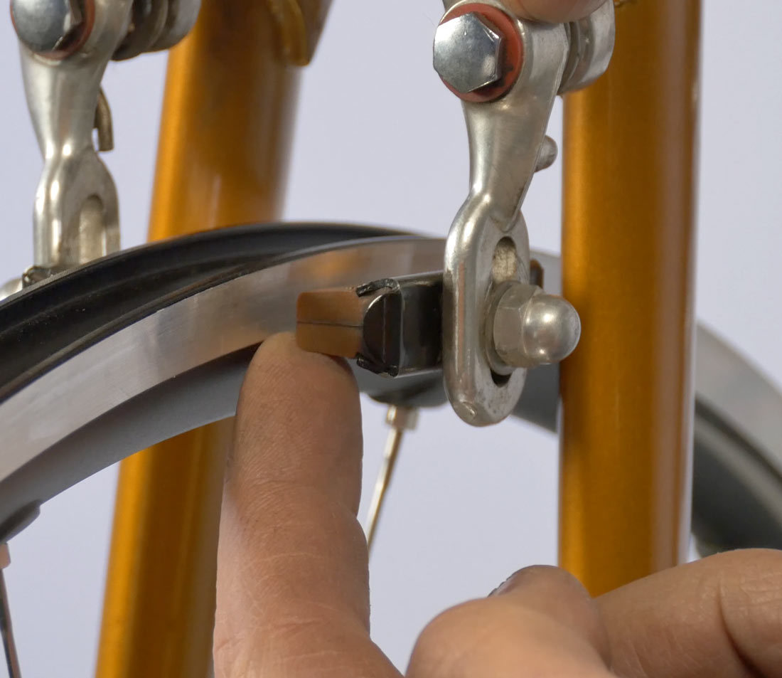
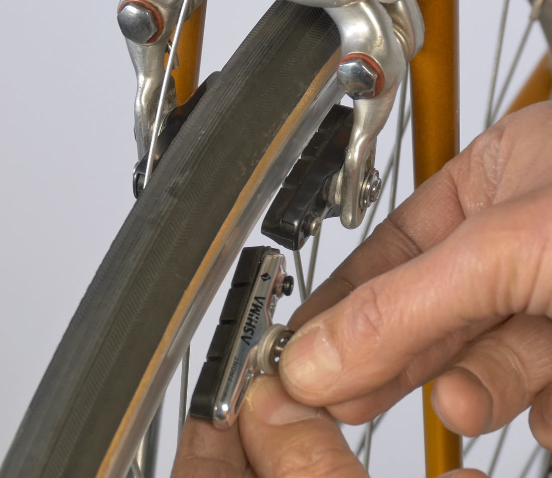
Pads are adjusted up and down for height. Loosen the pad mounting nut to adjust pad height on the rim braking surface. The bottom edge of the braking surface should be close to the bottom edge of the pad. As this pad thins and wears, it will make contact higher and higher on the rim braking surface. Before tightening, check that the front and back edge are the same height to the rim. Secure the mounting nut to approximately 5 Nm. When tightening, hold the pad firmly so it does not rotate when the nut is tightened. Repeat the process on the other side.
Cable Attachment
Next, attach the primary cable from the brake lever. Although no pad toe has been set, it is easier to bring the pads to the rim with the cable and then set the pad toe.
Begin by backing out the barrel adjuster two or three turns. This will provide enough slack to work with once the cable is fully attached.
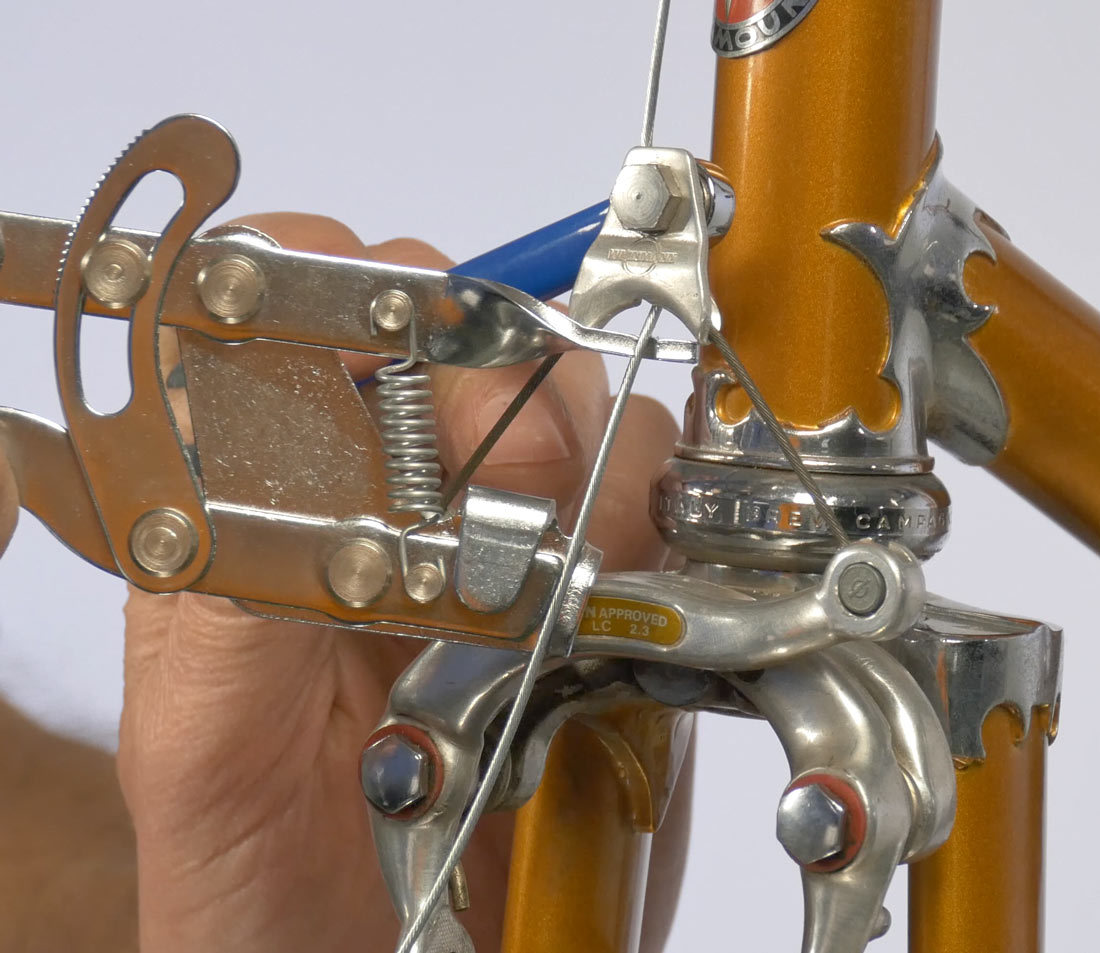
The straddle wire carrier will have a hole for the primary cable. Feed the cable through the hole with the manufacturer’s logo facing forward. This attaches around the straddle wire that connects both arms. Pull the arms upward before securing the pinch bolt. Use a fourth hand such as the Park Tool BT-2 when possible.
A common torque for the pinch bolt is 4–5 Nm. When properly tightened, the cable will become flattened in the pinch bolt.
Set Pad Clearance
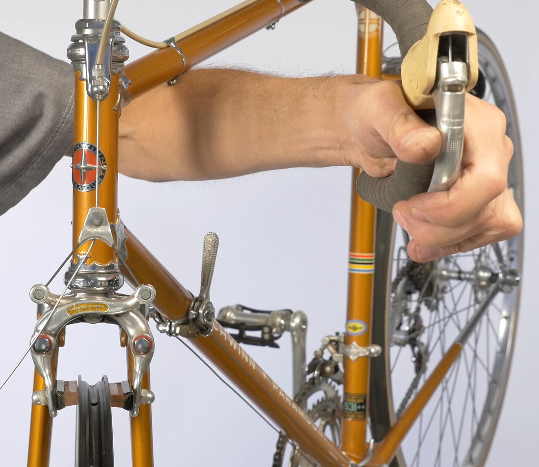
After the pinch bolt is tight, squeeze and pull the lever with force. This will test the torque to see if the cable slips. This also helps settle in the cable and housing. Next set the clearance from the pad to the rim by using the feel at the lever.
The lever is set to rider preference. Generally, there should be over an inch between the handlebar and the lever when the pads contact the rim. If the brake is too tight, the pads contact just as the lever is pulled. Adjust for more slack in the system by bringing the barrel adjuster in. If the setting is too loose, take the slack out with the barrel adjuster.
Centering
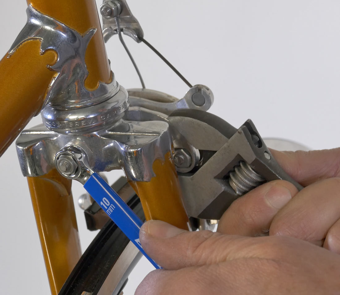
The next step is to center the pads to the rim. In the center pull, both pads must contact the rim at the same time. If one contacts the rim first, it will push the rim over toward the other pad.
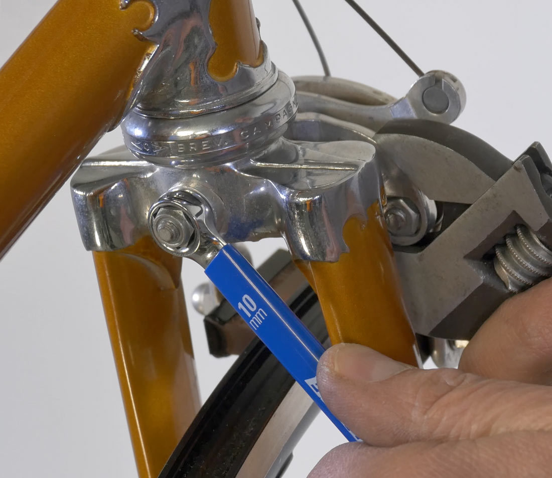
Use the bridge that connects both arm pivots to center the brake. Move the bridge and the mounting nut. Put an adjustable wrench on the bridge and a wrench on the back nut. Move the wrenches in the same direction, the same amount. Center the brake so the pads will contact the braking surface at the same time. This does not change the torque of the mounting nut.
Set Toe
The last pad adjust is called toe. This adjustment sets the pad so that the front or leading edge of the pad contacts the braking surface before the back edge. This reduces the tendency of the caliper to move back and forth quickly when the rim is contacted. Before doing this, a simple solution is to test ride the bike and see if it squeals. If there’s no squealing, then toe is not needed. Toe is put off until the end because the pads must first be centered and close to the rim.
Pads Without Concave Washer
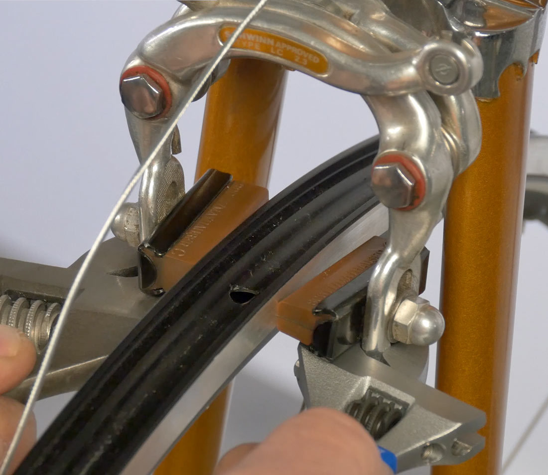
On the simple flat washer, flat-mount pad system, one way to get toe is to slightly bend each caliper arm. Use two small, adjustable wrenches, and engage under each side. It is important to bend the same amount. Draw the hands together so the back will flex outward. Just a little bit is needed. Try to be symmetrical, and test in between. When you have a slight gap at the back, that is proper toe.
Pads With Convex/Concave Washers
Some pad models use a convex and concave washer system. These curved surfaces allow the pad to rotate relative to the mounting bolt for an independent toe setting.
Finishing Touches
Lastly, install an end cap after cutting the cable. When cutting the cable, leave enough cable to grab and use a fourth hand tool. Trim the cable, install an end cap, and then crimp.
Related articles
Brake Pad Replacement: Rim Brakes View Article