Avid® Mechanical Disc Adjustment
This article will discuss the service and adjustment of the Avid® mechanical brake systems. For information on the disc rotor mounting, see Disc Brake Rotor Removal & Installation.
Getting Started
Disc brake systems use a caliper mounted near the dropouts of the frame or fork ends, and a rotor (disc) mounted to the hub. The brake pads are housed in the caliper and are forced into the rotor. Disc caliper brakes slow the bike by converting the speed and energy of the bicycle into heat. Disc brakes can be effective in wet weather where mud, dirt and water are a concern in braking. The system can generate significant heat from slowing the wheel and bike. Allow rotor and caliper to cool before touching or servicing.
Mechanical disc brake systems use calipers that are cable actuated, similar to rim caliper brakes, with an inner brake wire and housing pulled by a brake lever.
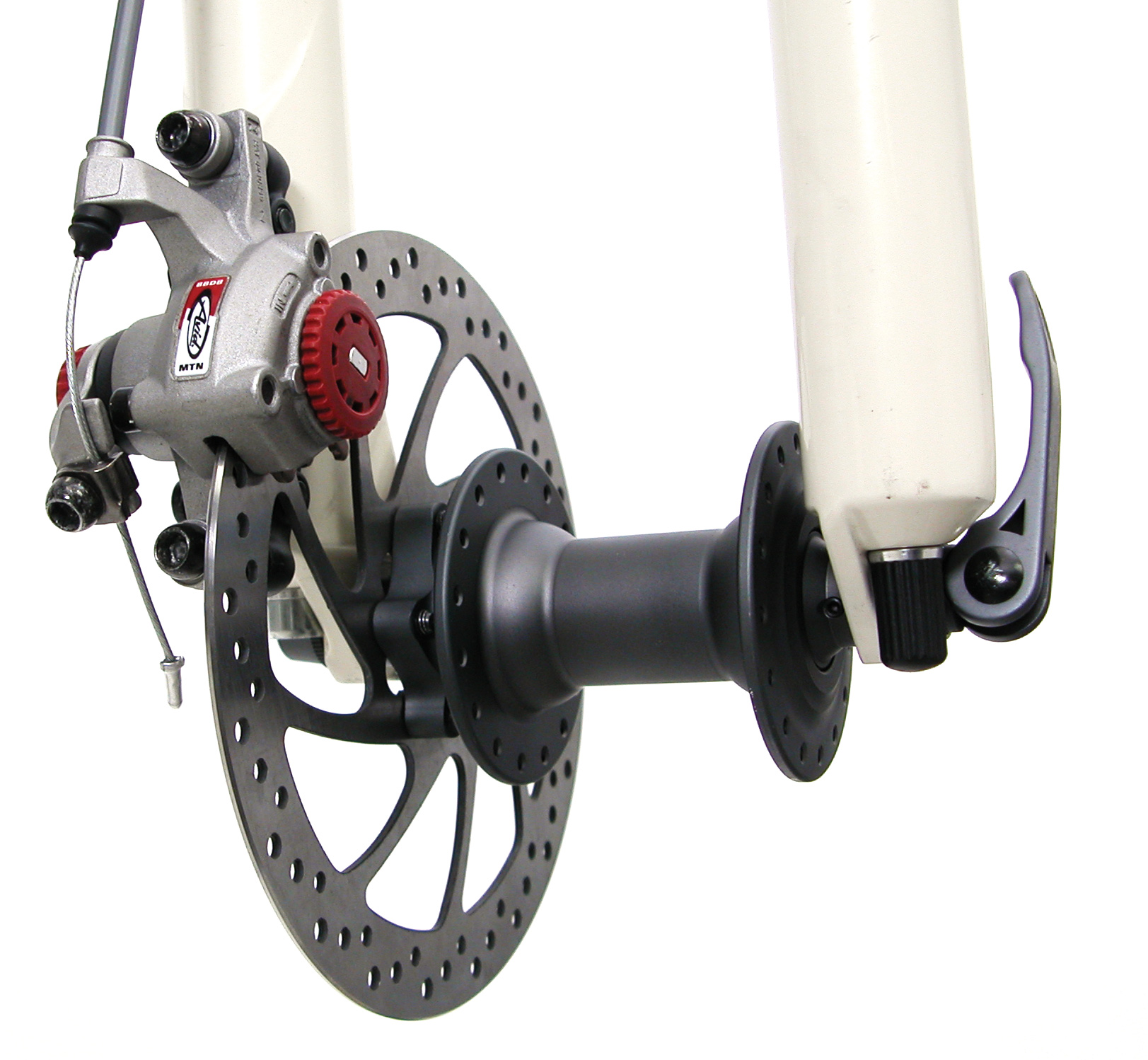
Mechanical disc calipers use two brake pads, one on each side of the rotor. Depending upon the design of the caliper, both pads may move to contact the rotor. However, alternative designs have one pad being fixed, with only one pad moving to contact the rotor. With this design, the rotor will flex to push against the fixed pad when the brake is used.
Flat handlebar brake levers used with mechanical disc calipers are compatible with the linear pull caliper rim brakes. The lever should be set for a comfortable reach and secured to the bar. The brake housing and brake wire are the same as with rim caliper brakes. Prepare housing and wires as with rim caliper brakes.
Caliper Adjustment
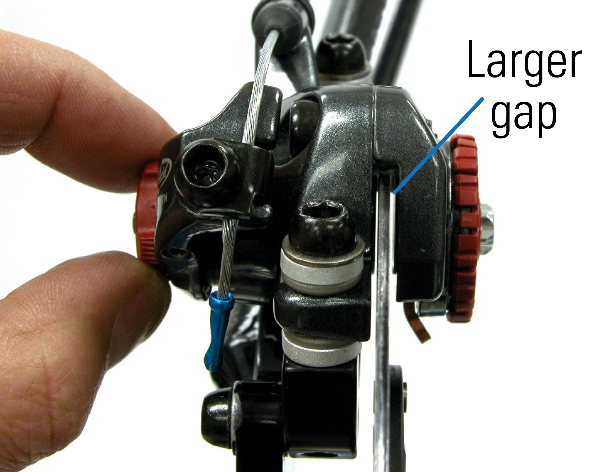
The Avid® caliper design is to have the inner pad-to-rotor gap about twice as large as the outer pad-to-rotor gap. It can be difficult to measure and achieve this ratio, but the brake will still perform even if the ratio does not achieve this exact proportion.
The outer pad moves toward the rotor when the caliper-actuating arm is pulled by the brake wire. The inner pad can be adjusted toward or away from the rotor with a pad-adjusting knob, but it is fixed during braking. The moving pad flexes the rotor toward the fixed pad when the brake is operated. The moving outer pad also uses an adjusting knob to position the pad relative to the rotor. The dial uses an indent system, with 16 per revolution. One complete revolution moves the pad approximately 1mm.
Caliper Alignment
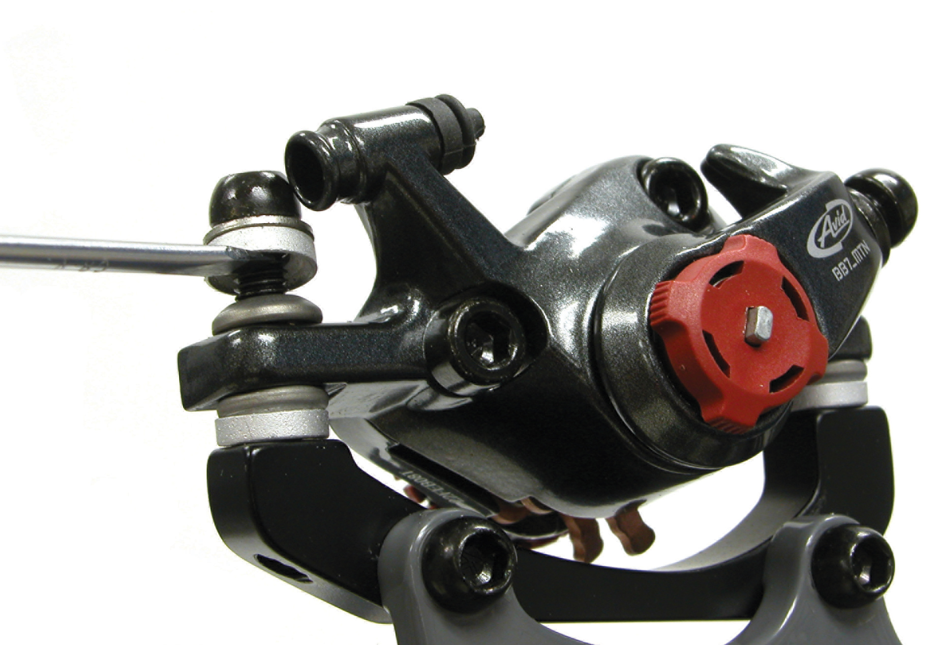
The Avid® mechanical disc brake for MTB bikes uses a brake lever designed for linear pull brakes. Pad adjusting knob moves pad position relative to rotor. Avid® disc caliper brakes use a ball-and-socket system for the caliper mounting bolts. This fixing system is similar to many brake pads on linear pull caliper rim brakes. This system allows easy alignment of the brake caliper to the rotor.
The procedure for Avid® mechanical caliper pad alignment is as follows (note: for calilpers with a pad adjustment screw for inner and outer pads):
- If the caliper is attached to an adapter bracket, check that the bracket is fully secured to the frame or fork.
- Loosen caliper-mounting bolts so the caliper is loose on bracket or post mounts.
- Slacken cable with adjusting barrel or loosen brake wire pinch bolt if it is secured.
- Check that both pad adjusting knob dials are turned fully counter-clockwise to move pads fully away from rotor.
- Turn the outer pad-adjusting knob approximately 1/2 turn clockwise.
- Turn the inner pad-adjusting knob clockwise until inner pad fully secures and locks rotor. This helps aligns caliper body and pads to rotor face. NOTE: Fine tuning of pad alignment is still necessary.
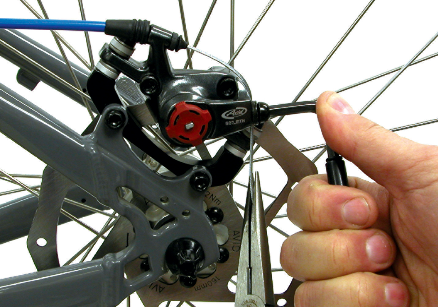
- Snug each caliper-mounting bolt. Alternate turns to tighten one bolt and then the other until both are fully secure.
- Draw slack from the brake wire and secure pinch bolt. Do not allow caliper arm to move upward when drawing slack from brake.
- Set pad clearance. Loosen outer pad adjusting knob approximately 1/4 turn counter-clockwise. Loosen inner padadjusting knob approximately 1/2 turn counter-clockwise. Inner pad (fixed pad) to rotor gap should appear larger than the outer pad to rotor gap.
- Squeeze lever to test caliper brake. Adjust lever modulation setting by moving pads inward or outward from rotor by using both pad-adjusting knobs. To maintain the 2:1 ratio, turn the fixed pad-adjusting knob twice as many clicks as the moving pad-adjusting knob. For example, if a looser modulation is desired, turn the inner pad-adjusting knob counter-clockwise 4 clicks and the outer pad adjusting knob counterclockwise only 2 clicks.
The caliper-actuating arm is designed to operate from a fully open position. Set cable tension at the adjusting barrel so actuating arm is fully opened or returned. Do not use the brake lever adjusting barrel or cable pinch bolt to account for pad wear. Caliper arm may bottom out on caliper body and prevent the pads from pressing on rotor.
Pad Removal and Replacement
As pads wear, use pad-adjusting knobs to move pads closer to rotor. As you ride, both pads will wear thinner at the same rate. Turn the both the fixed pad adjusting knob and the moving pad adjusting knob the same number of clicks to maintain the 2:1 ratio of pad to rotor spacing. Brake pads should be removed and replaced if the pad thickness, including the metal holder, is less than 3mm.
Avid® mechanical brake pads should be removed and replaced if the pad thickness, including the metal holder, is less than 3mm.
The procedure for Avid® mechanical caliper pad removal and replacement is as follows:
- Mount bike in repair stand and remove the wheel.
- Loosen each pad adjustment knob an equal amount.
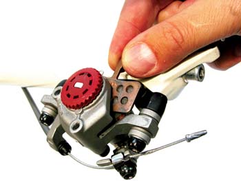
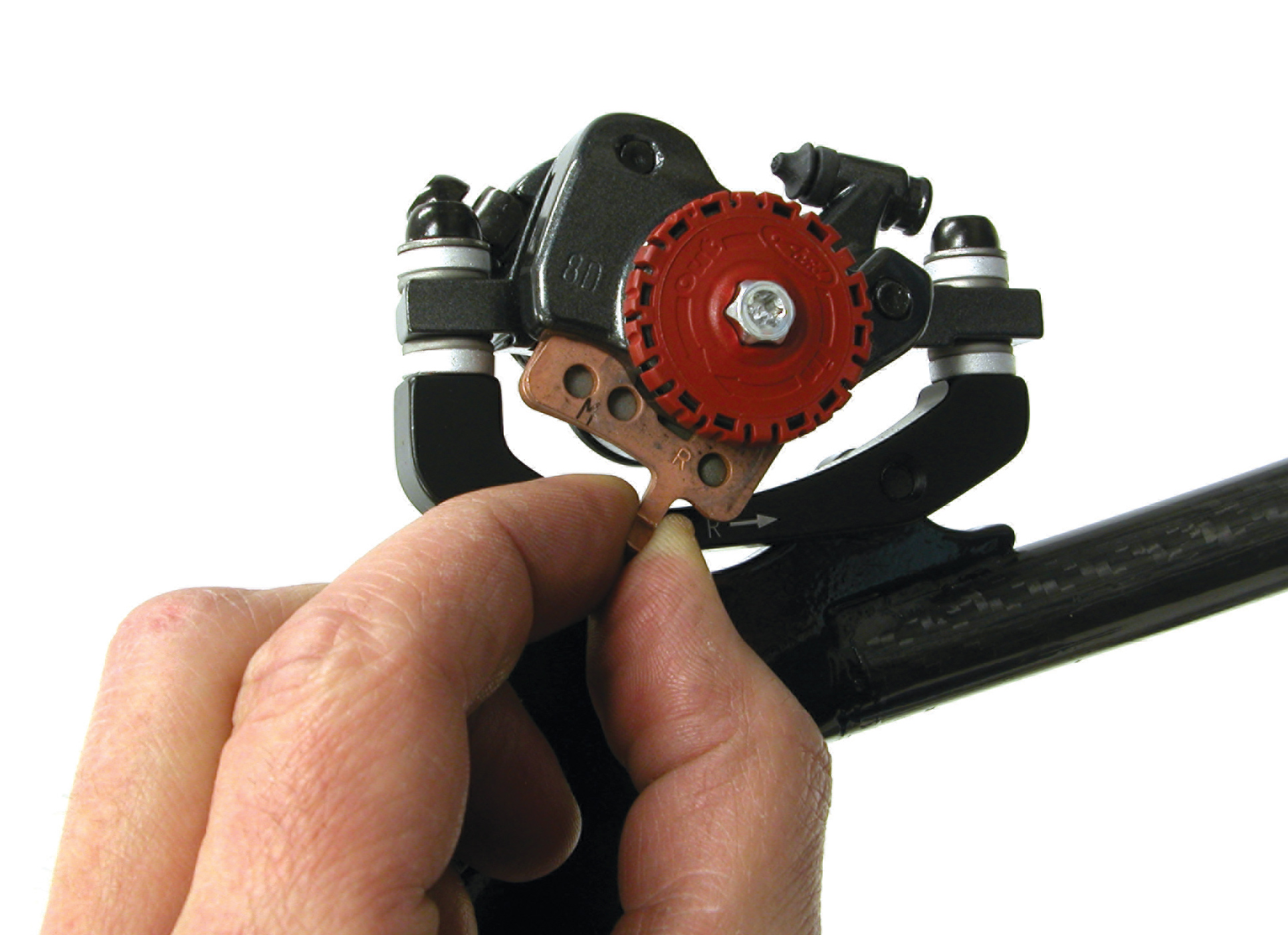
- Grab lever at end of pad and push toward center of caliper body, pulling pad outward and away from caliper. Repeat process for second pad.
- Push lever to center of caliper body and lift to remove. Note orientation of pad return spring and remove spring from pads.
- Place new pads over pad return spring. Spring should be sandwiched between new pads. Installation lever is set asymmetrically on pad.
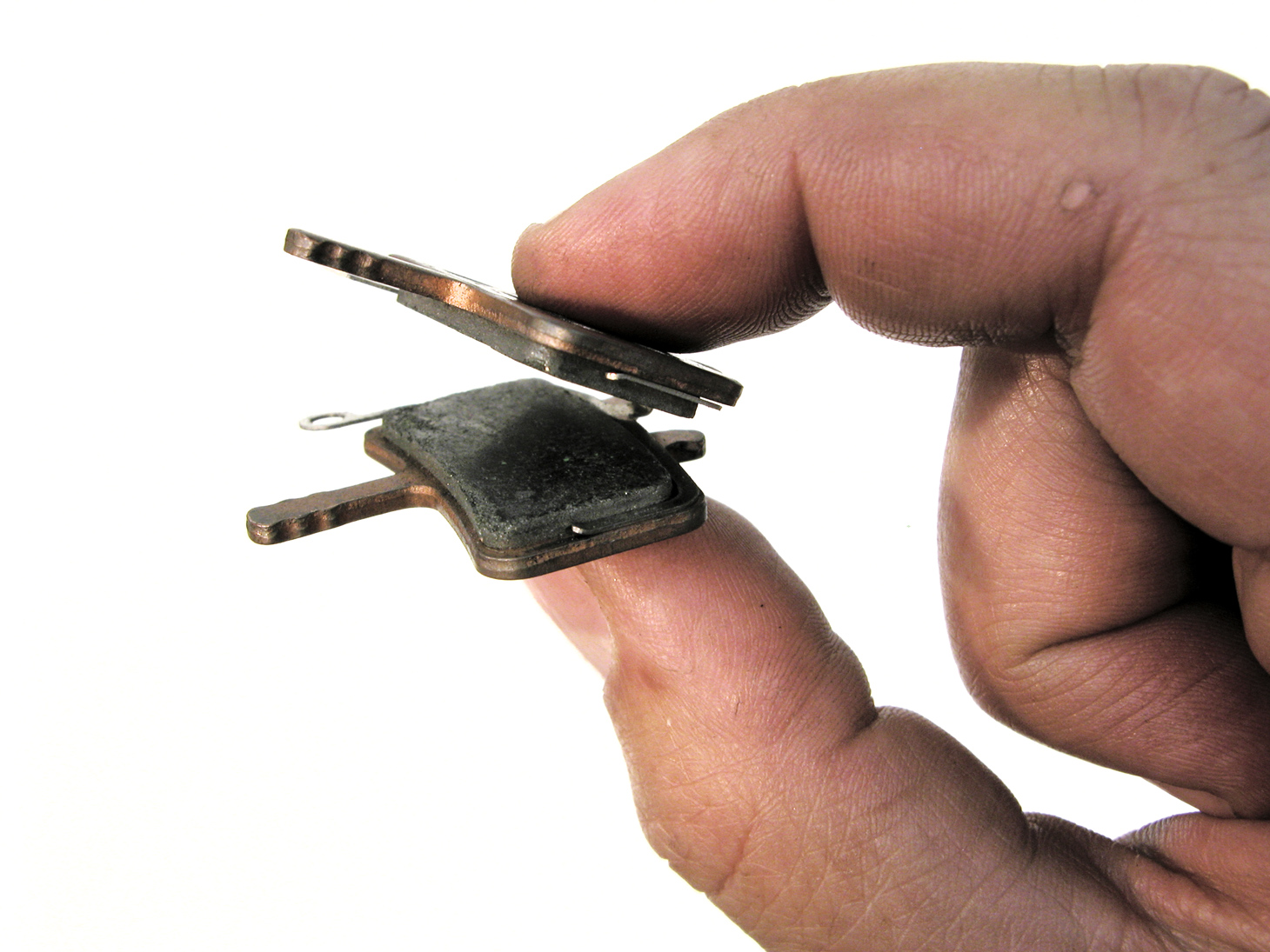
- Align bridge of spring with caliper boss locators. Gently squeeze return spring and pads. Engage pads into caliper body. Pad installation lever orients away from brace bolts. Push return-spring and pads into place. Pad locator will engage bosses in caliper boss.
- Push pads into caliper body.
- Install wheel.
Related articles
Disc Brake Squeal: A Case Study View Article