SRAM® HammerSchmidt™ Crankset Installation
This article will discuss the installation of the Truvativ® HammerSchmidt™ front transmission system.
Getting Started
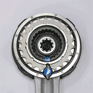
The HammerSchmidt™ is a two-speed gear system designed into the front crankset. It consists of a special right side drive crank containing internal planetary driven gears, a collar assembly plate, bottom bracket bearing, left crank, and shifter (figure 1). The kit also includes spacers to exactly position the collar assembly plate.

A transmission gear system allows the sprocket (chainring) to be driven at a different rate then the crankarm. A conventional crank with chainring will turn together, with one rotation of the crank equal to one rotation of the chainring. The HammerSchmidt™ has two drive modes. In the fixed arm mode, with the inner ratcheting gear disengaged, the arm will turn with the ring as with conventional cranks. When the lever is released and the pawls engage the inner gear ratchet, the chainring will turn more than the crank. When driving off the planetary system, the ratio of driving increases to approximately 1-to-1.6. A 22t ring in the photo below will to be effectively equal to driving a 36-tooth ring. If replaced crank chainring is replaced with a 24t ring, the “big ring” equivalent will be a 38-tooth ring. Shifting is permitted during coasting, back pedaling and pedaling under load.
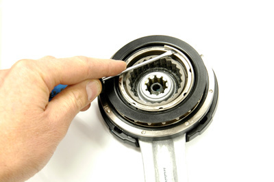
The operation of this mechanism is apparent event when the crank is off the bike and the ring is back-pedaled. In Figure 2, the chainring is turned counter-clockwise, which turns the inner ratchet gear clockwise. A logo sticker was placed on the outer chainring and aligned with blue tape on the inner ratcheting gear. The outer ring is turned one full revolution. Note that the inner ring travels one complete revolution while the outer ring is only about 60% around its first revolution. When the outer chainring has made one full revolution, the inner ratchet gear has rotated approximately 1.6 times.
The crank can be fitted with different sized rings. These rings are a proprietary design and do not interchange with other systems. Remove the retaining ring on the back side of the crank using a small tip screwdriver such as the SD-3 (figure 3). Pull off the ring cover and the chainring. Rings are available in 22 and 24 teeth.
Frame Preparation
The HammerSchmidt™ is designed to secure to the ISCG or ISCG 05 mounting tabs that are a permanent part of the frame. The ISCG mounts consist of three special frame holes around the bottom bracket shell that allow the installation of various chain retention systems. The HammerSchmidt™ is designed ONLY for frames with permanent ISCG mounts. Adaptor plates bolted between the shell and bottom bracket are not acceptable. The system will load the mounting tabs torsionally, and it is important the tabs be integrated as part of the frame.
The HammerSchmidt™ utilizes a collar assembly plate that mounts directly to the ISCG tabs. This assembly collar plate secures simultaneously against both the bottom bracket shell face and the ISCG tabs. The tab surfaces should be machined to insure they are parallel to the surface of the bottom bracket shell. Additionally, and more importantly, the distance from the shell face to the tabs must be cut to be equal to the predetermined supplied spacers thickness. The kit comes with spacers in sets of three in thickness of 0.5, 1, 1.5, 2, 2.5, and 3mm. In some cases, no spacer is used at all. By using these spacers the transmission system planetary and sun gear will be correctly aligned.
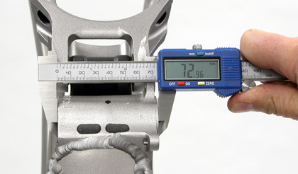
Begin frame preparation by measuring the width of the bottom bracket shell (figure 4). Truvativ specifies certain tolerances for the three common shell widths:
Nominal 68mm shells: 67.8 to 68.3mm
Nominal 73mm shells: 72.8 to 73.3mm
Nominal 83mm shells: 82.8 to 83.3mm
If the shell is wider than the tolerances it can be machined narrower as needed. If a shell is narrower then the tolerances, it may be necessary to machine and then add a spacer according. If the shell face is very close to or equal to the lower end of the tolerance, consider not machining this shell face.
Begin by facing the bottom bracket shell face as you would normally prepare a frame. This ensures the bearing surfaces of the bottom bracket spindle are parallel and square to the axis of the thread. If using the BTS-1 leave the threaded inserts in place. These will guide the mounting tab cutter.
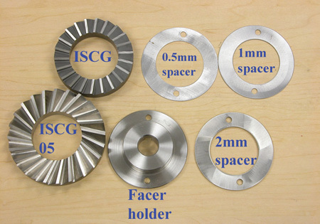
Truvativ makes and sells the HammerSchmidt™ Facing Tool Assembly for the facing the mounting tabs (figure 5). The cutter fits the handle of the BFS-1 bottom bracket facing set. The holder also fits the handle of the BTS-1 tapping and facing set. A series of shims allow the cutter to reach and cut mounting tabs that are inboard of the bottom bracket shell face.
Before facing, inspect the mounting tabs relative to the shell face. The tabs may be flush with the shell face (figure 8). The tabs may also be lower (inboard) of the shell face (figure 7).
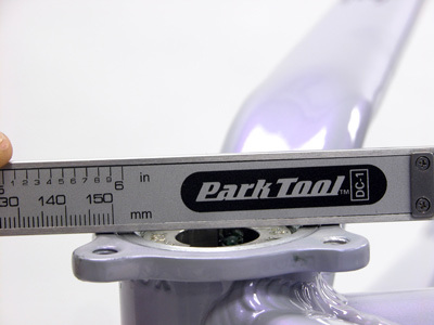
Figure 6. Shell face and ISCG tabs are on the same plane, or flush
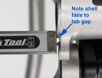
Figure 7. ISCG tabs are further inward, or "lower", then the shell face
The Truvativ cutting tool bolts to the Travativ mounting plate. The inner perimeter of the mounting plate will push against the shell face, with no facing occurring. With no spacers between cutter and holding plate, the cutter will be in the same plane as the shell face. By installing spacers behind the cutter, the cutter will be positioned further and further inward relative to the shell face.
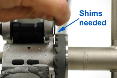
To select the correct shim, install the cutter on the holder without spacer and install the holder on the handle of the BFS-1. Do not secure the cutter to the holder at this time. Insert the handle with cutter through the right side of the bottom bracket. If there is a gap between the cutter and tabs, select the closest shim or combination of shims that will, by the smallest margin, not fit into the gap (figure 8). The shims then allow the cutter to reach the tabs and to cut the desired predetermined distance(s) from shell face to tabs. The tab to shell face distance will then correspond to the bracket spacers provided in the kit.
Pull handle from bike and pull mounting plate from tool. Secure cutter and appropriate shims to holder with supplied screw (figure 9).
Rotate facer clockwise only to face shell face using normal facing techniques (figure 10). Continue cutting until the cutter removes no more material (figure 11). At this point, the center of the cutter holder will be pressing against the shell face. This process sets the depth from the shell face to the ISCG tabs. Remove the cutter, remove the threaded guides or taps, and clean the bottom bracket area.
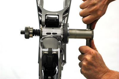
Figure 10. Face ISCG tabs until no more material is removed by cutter
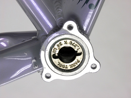
Figure 11. ISCG tabs faced until flush with shell face. No spacers will be required with this mount.
Bottom Bracket Installation
Install the HammerSchmidt™ bottom bracket. If the frame is a 68mm shell use, for each bearing cup, the supplied 2.5mm spacer. This effectively widens the shell to 73mm standard, plus or minus tolerances. Prepare threads with grease or anti-seize. Install drive-side (right side) cup first turning counter-clockwise. Secure drive side and non-drive side the Park Tool BBT-9 (figure 12).
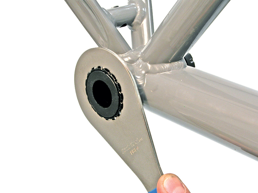
Figure 12. Install and secure bottom bracket
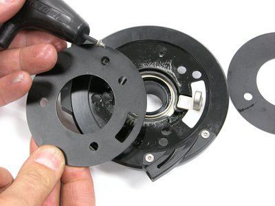
Figure 13. Remove plate to switch between ISCG standards
Install the collar assembly plate. The plate may be change from the ISCG to the ISCG 05 sizing. Remove the cable pinch bolt and washer. Loosen and remove the single screw holding the plate using a T-10 star-shaped wrench (figure 13).
If the ISCG mounting tabs are flush with the shell face, no spacers are required. If the mounting tabs are inboard of the shell face, use the thickness of spacers corresponding to the thickness of shims used during facing of the tabs (figure 14). NOTE: 68mm shells use the supplied 2.5mm spacer under the bottom bracket bearing cup. This effectively moves the collar assembly outward 2.5mm. If the mounting tabs were flush with the shell initially, the collar assembly should use the 2.5mm set of plate spacers.
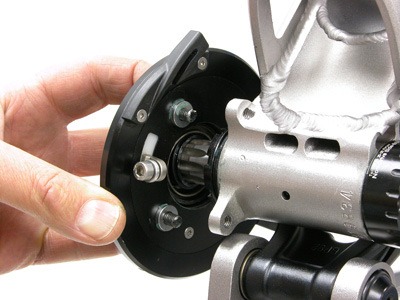
Figure 14. Installation tip: use a dab of grease between spacer and collar plate to help hold spacers while installing
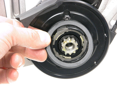
Figure 15. Install seal on collar assembly
Inspect that no part of the assembly collar plate is contacting or rubbing against part of the frame, such as stays or struts. Secure each collar assembly plate bolt. Install the rubber seal (figure 15).
Route housing from the shift lever to the housing stop on the assembly collar plate. In some cases, it may be necessary to route full housing from the lever to the stop (figure 16). Secure housing as necessary. Pull out slack from the cable and secure the pinch bolt.
Adjust cable tension so there is no cable slack, and use the shifter to check movement of the pawls at the center of the collar assembly plate. Note that with no cable tension, the pawls stick out. In this position the teeth are catching the inner ratchet gear of the crank and turning the chainring through the planetary gears (figure 17). Pull the lever to the alternate position, and the pawls will rotate into the collar (figure 18). In this position, the crank and ring are “direct drive” with the ring and crank turning together.
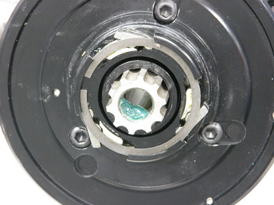
Figure 17. Pawls of collar assembly are out and able to engage ratchet gear of crank
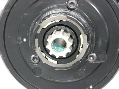
Figure 18. Pawls move inward when lever is moved to second position
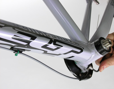
Install the cranks. Spline fitting on this crank system is similar to other spline systems such as ISIS Drive. Use care to engage the crank spline with axle splines as the crank slides over spindle. Secure each arm to 48-54 Nm torque (figure 19).
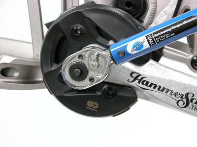
Figure 19. Secure cranks with torque wrench
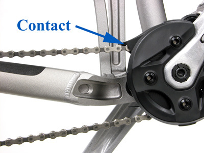
Figure 20. Chain contact with guide should be corrected
Before installing the chain, turn the cranks and try the shifter. Notice movement of the chainring relative to crank in both shift lever positions. Install and size the chain as with any derailleur chain. For suspension bikes, account for any rear axle movement during linkage movement. Note the position of the upper built-in chainguide. The chainguide must not press downward on the chain (figure 20).
Adjust the chainguide position by removing and repositioning the guide as necessary over the multiple hole options (figure 21).
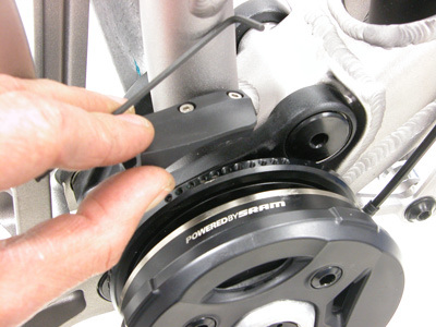
Figure 21. Remove and reposition guide as necessary
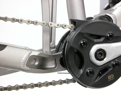
Figure 22. Adequate chainguide position
Test the guide location in all chain positions on the rear cassette (figure 22). The chain will rise up as it shifts inward.
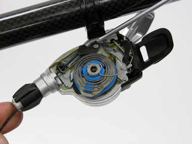
The shift lever cable can be service similar to other SRAM system shifters (figure 23). Loosen the four point nut on the top cap. The nut should only require hand loosening, no tool is typically needed. Use a small tipped screwdriver to remove the cable end from the cable carrier.
Related articles
Crank Removal and Installation: Campagnolo® Power Torque™ View Article
Crank Removal and Installation: Three-Piece View Article
Crank Removal and Installation: Self-Extracting View Article
Crank Removal and Installation: Two-Piece Compression Slotted View Article