Shimano® Hydraulic Brake Service and Adjustment
This article will review the procedures to bleed Shimano flat bar hydraulic brakes using the Park Tool BKM-1.2 or BKM-1 Bleed Kit.
Preliminary Information
- BKM-1.2 Hydraulic Brake Bleed Kit (Mineral)
- Appropriate mineral oil for the system
- Hex wrenches
- PS-1 Pad Spreader, PP-1.2 Piston Press, tire lever or cone wrench
- Clean rags
- Isopropyl alcohol
- Angle finder
- 7 mm wrench
- Toe strap or zip ties
- Spent fluid container, such as a bottle or bag
- Safety glasses and gloves
Hydraulic braking systems require that there is no air in between the caliper pistons and the primary piston. Air bubbles will compress and cause the brake to feel soft when the lever is pulled with force. Additionally, the fluid can become dirty with use and should be changed.
With any brake bleeding work, consider the following:
Brake bleeding is considered an advanced service procedure, and requires a thorough technical knowledge of the braking system. If in doubt, or if this procedure is not working, contact the brake manufacturer for model-specific information.
It is important to always use the appropriate brake fluid for the brake being serviced. Never use DOT brake fluid in brakes designed for mineral oil, or vice versa. Never share bleed kits between DOT fluid and mineral oil systems. Mixing fluids can cause damage to components and lead to brake failure, which is dangerous.
Anticipate any inadvertent fluid drips or spills on the floor by putting down a cover. Dispose of any fluid in accordance with your local waste disposal authorities. If in doubt or if your procedure is not working, contact the brake manufacturer’s website for their model specific information.
This article will use the Shimano XT M800 as an example for most steps of this procedure. Illustrations of the proper angles to set the funnel for all styles are also provided. If you are unable to find your brake lever style below, see si.shimano.com for technical information.
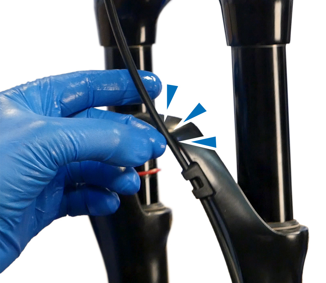
Mount the bicycle in a repair stand. Inspect the lever for a reach adjustment screw. Note its current position, then use the adjustment screw to bring the lever away from grip as far as it will go.

Potential location of reach adjustment screw
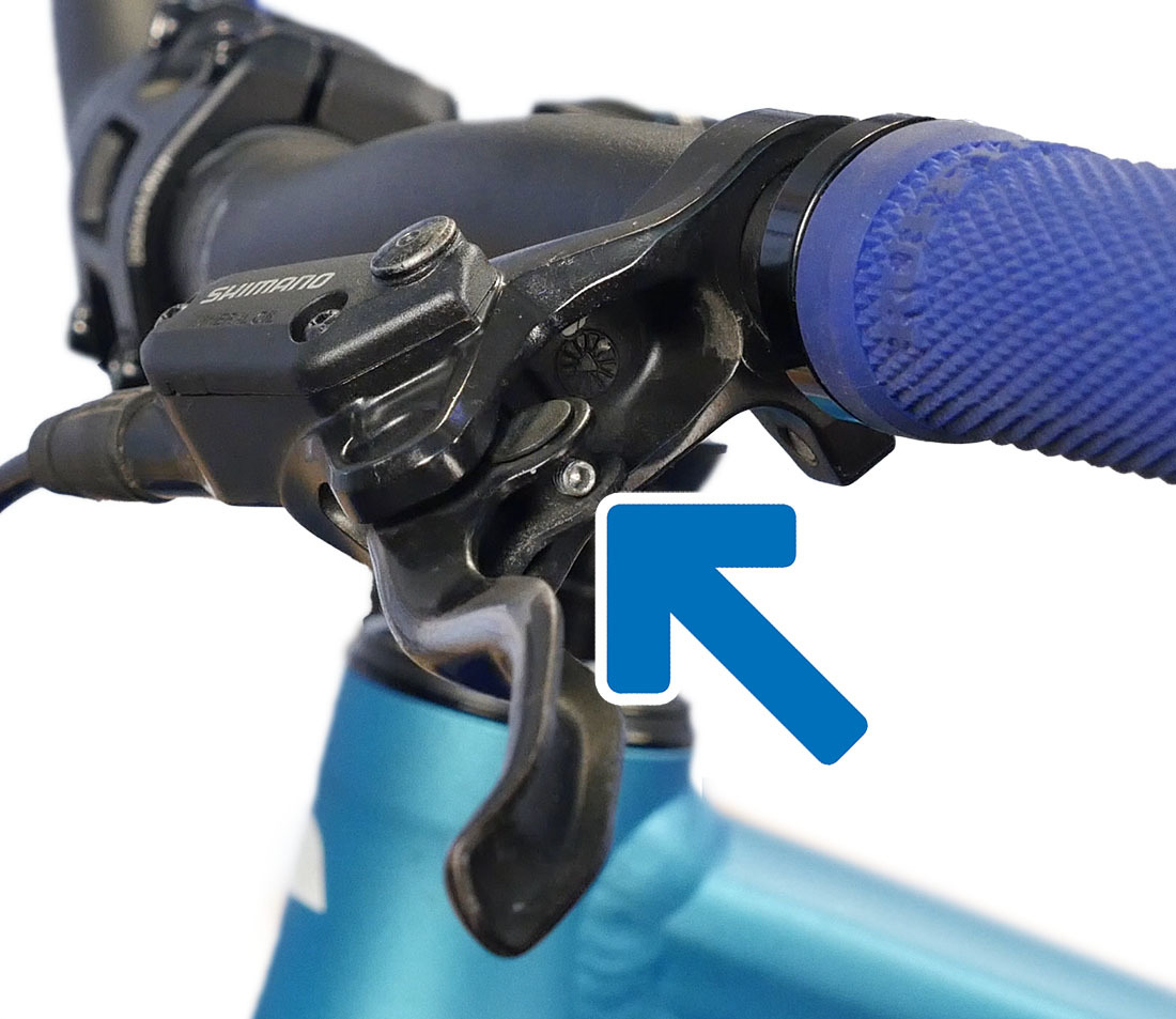
Potential location of reach adjustment screw
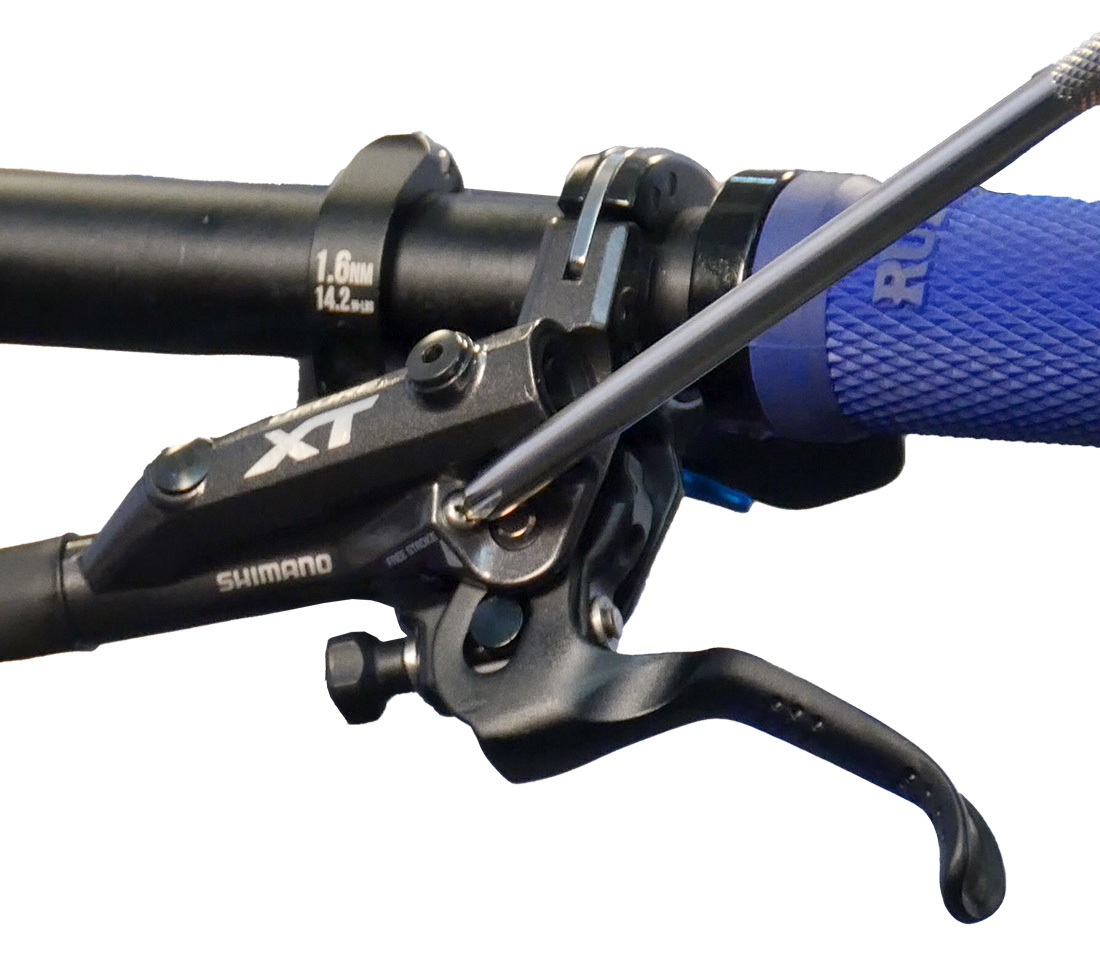
Some lever models also have a free stroke adjustment screw. From all the way tight, turn it 3 or 4 turns counterclockwise.
Remove the wheel. Rotate the bike so that the hydraulic hose is consistently traveling upward from the caliper to the lever.
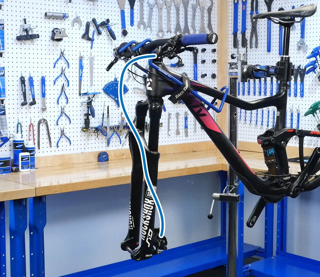
For front brakes, this position is fine.
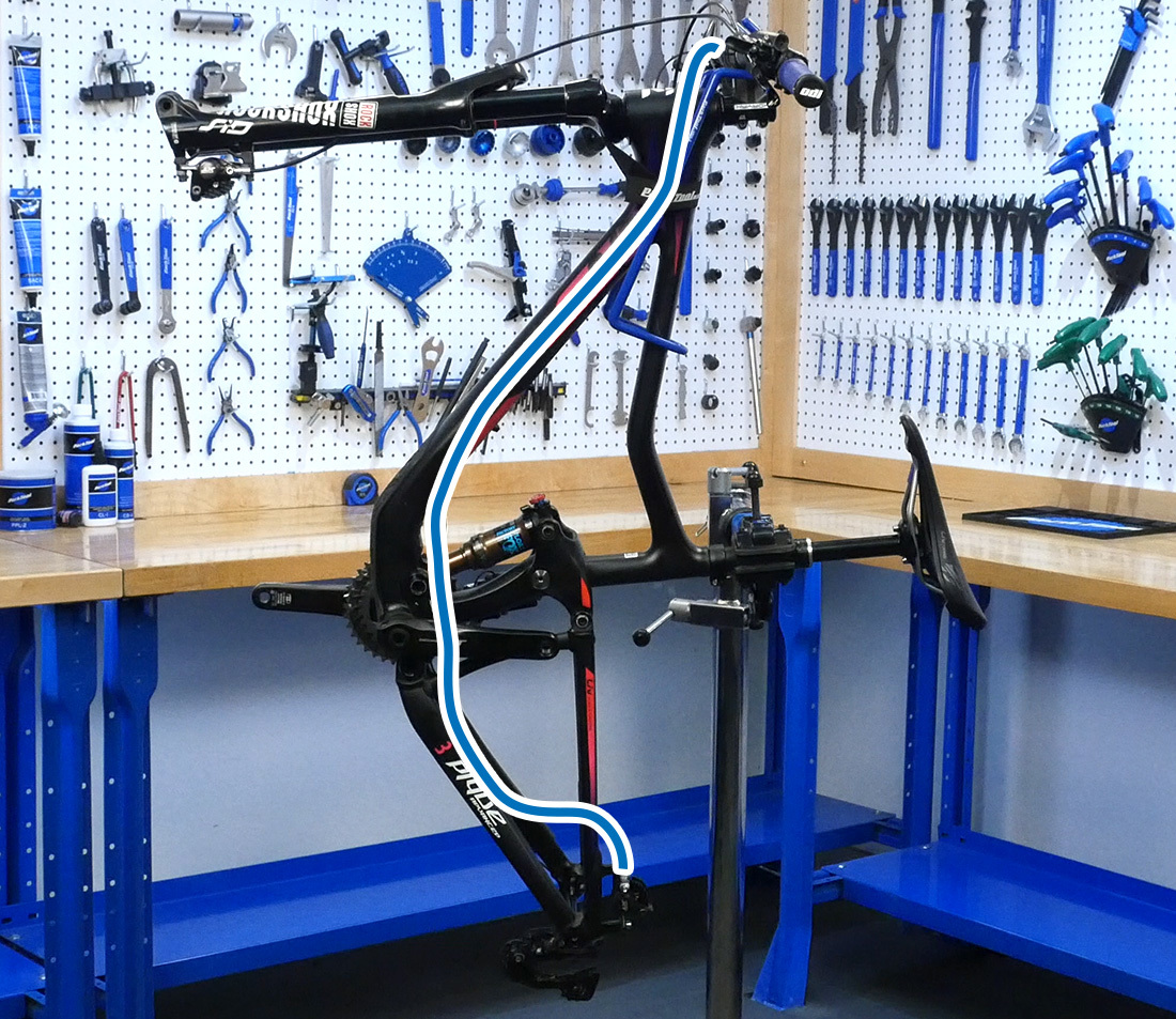
On rear brakes, the bike may need to be tilted. Lower the stand if necessary.
Remove the brake pads from the caliper. Store in a clean place.
Using a piston press or an appropriate flat tool (such as a tire lever or cone wrench), reset the pistons back into the caliper body.
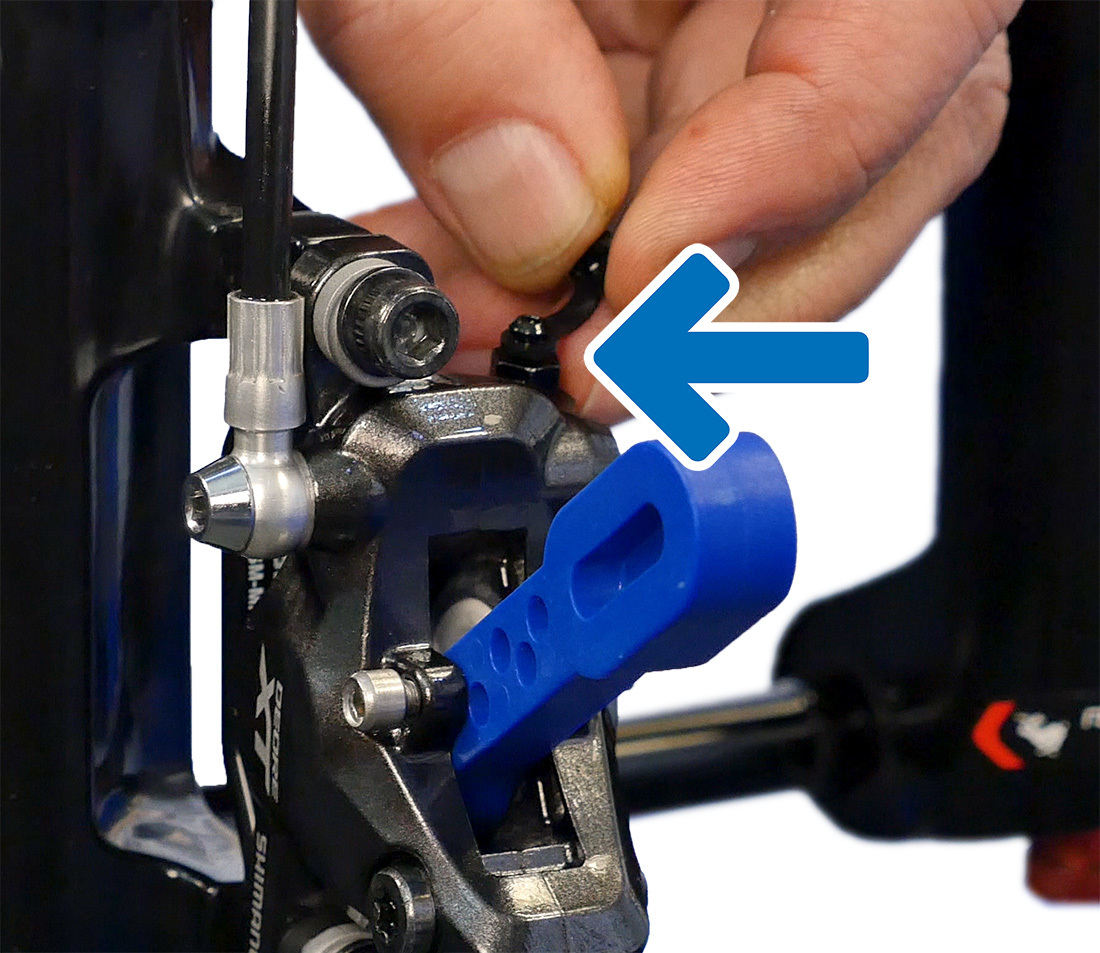
Install brake bleed blocks between the pistons. Hold the block in place using the brake pad screw from the caliper. Finger tight is fine.
Completely remove the bleed nipple cover and store it in a safe place. If working on the front caliper, it is sometimes better to remove it from the mount. This allows better access to the external bleed nipples.
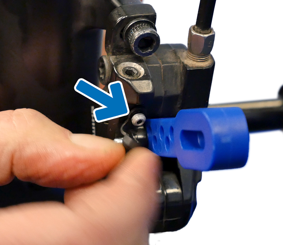
NOTE: The caliper bleed location can vary. See the examples below:
This caliper bleed nipple is located on top of the caliper body
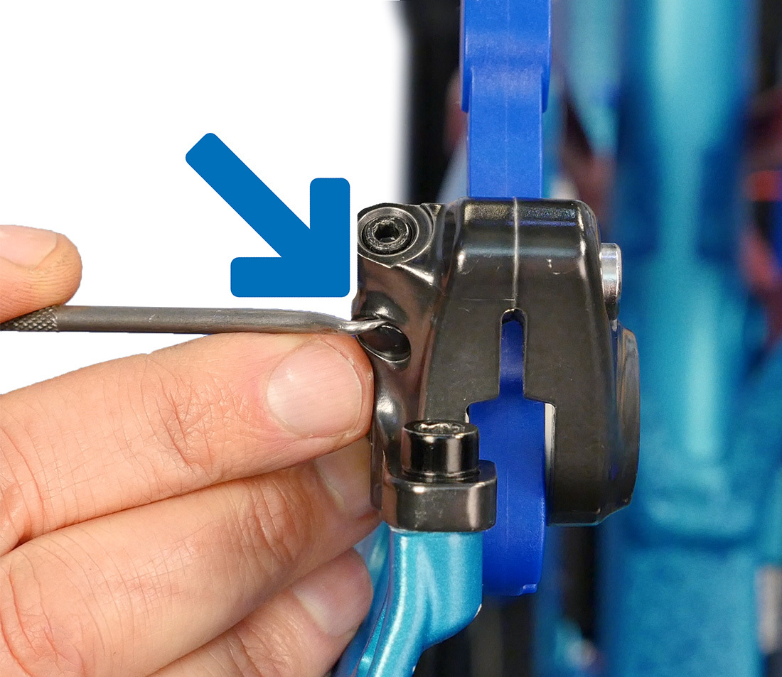
On this caliper, there is an internal nipple below a cover
Up at the lever, locate the bleed port screw. Remove the screw and O-ring. Store these in a clean, safe place.
The lever port screw is an M5 thread, the same as the thread on the bleed funnel included in Park Tool’s mineral oil bleed kit. However, if you first thread the funnel into the purple adapter (part #2623A), also a M5 thread, it makes it easier to correctly align the threads. Use care not to cross-thread the adapter as you snug it onto the funnel and the bleed port.
Remove the stopper from the bleed funnel. Viewing the bike directly from the side, take note of the bleed funnel’s vertical alignment. Rotate the lever as necessary until the funnel is 45 degrees forward from vertical.
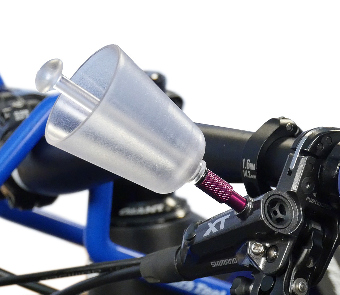
Bleed funnel (with adapter) installed into the bleed port
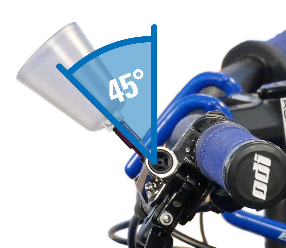
Funnel oriented at 45 degrees
Attach the syringe holder above the caliper.
Bleed Kit Preparation
Find the hose with one open end (#2593.2A — BKM-1) or the hose with one barbed end (#2574A — BKM-1.2). Thread the threaded end onto the syringe, snugging it gently.
If using the open-ended hose, slide the hose compression sleeve (#2588.2) over the end of the hose. Pull it up toward the syringe.
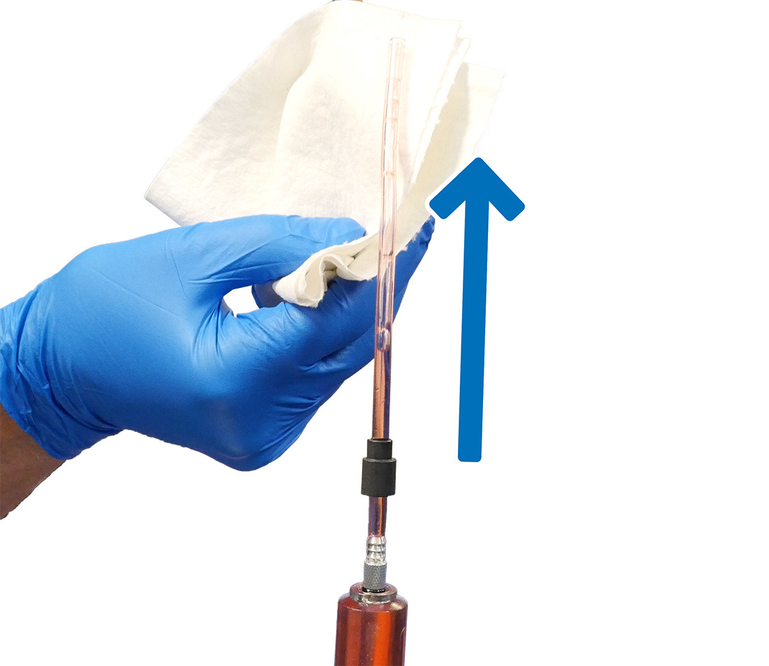
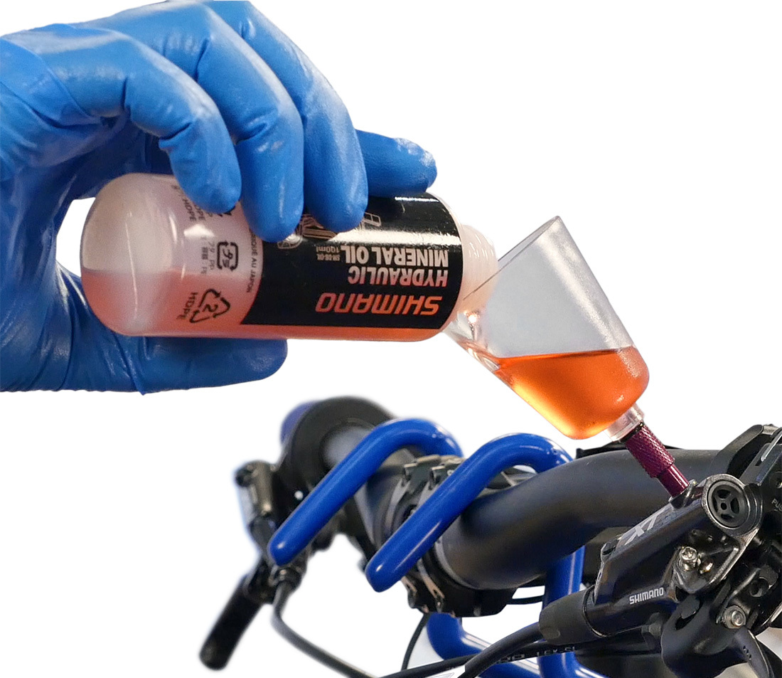
Fill the syringe about 2/3 full with the appropriate brake fluid. Hold the syringe upright and pull back to clear the tubing. Then slowly and carefully push the plunger until fluid comes up to the end of the tubing.
Place the syringe into the syringe holder.
Bleeding Procedure
Bicycle Preparation
Place a 7 mm box end wrench over the nipple. If using the compression sleeve, slide it down to the end of the hose. Push the hose end securely over the nipple.
Using the wrench, open the nipple one half turn. For calipers with a bleed port screw, loosen the bleed port screw one half turn.
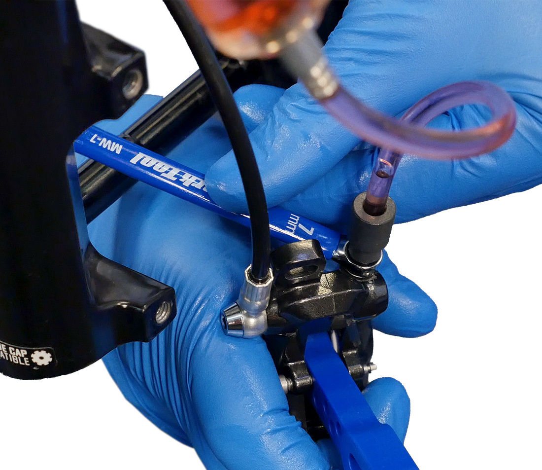
This example features a bleed port screw.
Push almost all — but not all — of the fluid into the caliper through the system and up into the bleed funnel. Look for any bubbles appearing in the funnel. That indicates air from the system is being expelled. If the fluid was dirty, continue to push until you see clean fluid entering the bleed funnel.
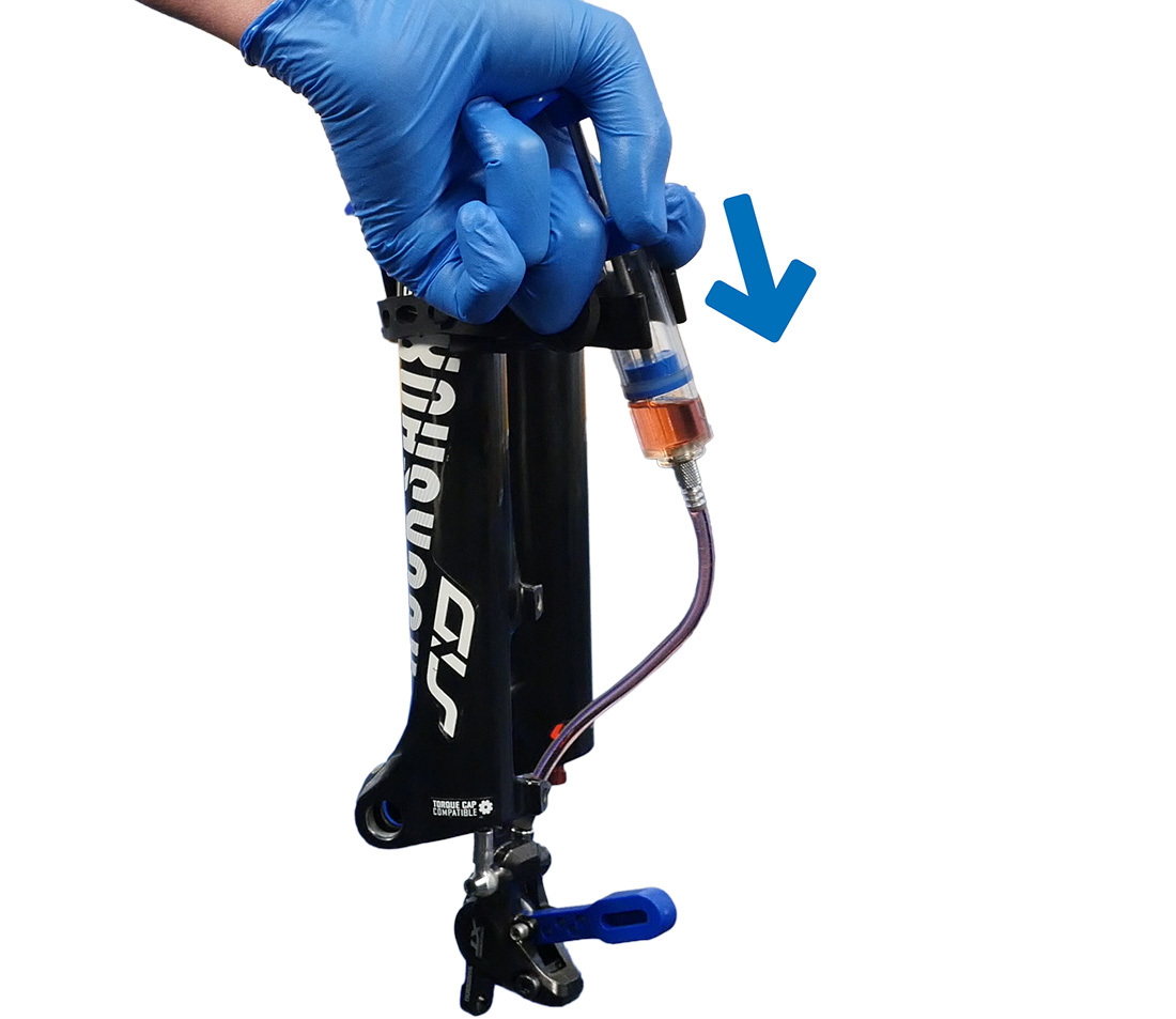
Push fluid from the syringe through the system
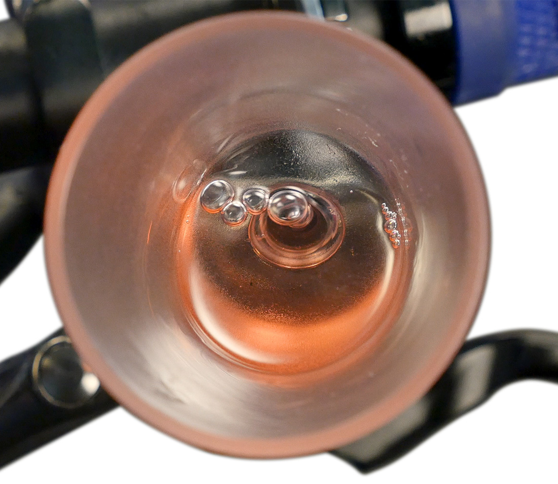
Bubbles emanating from the system
Close the bleed nipple at the caliper. Now the syringe can be removed from the caliper. Pull back a little on the syringe as you disconnect it from the caliper in order to minimize dripping. Remove the syringe holder.
If the fluid in the funnel was dirty, install the funnel stopper. Remove the funnel and dispose of the dirty fluid. Reinstall the funnel onto the lever, remove the stopper and refill the funnel over half full with fresh fluid.
The next step is to reverse the flow of fluid from the bleed funnel downward and out at the caliper. Select the hose that has no fitting on either end. Install the compression sleeve on one end. Insert one end into a plastic bag or other receptacle. Secure the hose inside the bag with a zip tie. Attach the hose to the bleed nipple and secure with the compression sleeve.
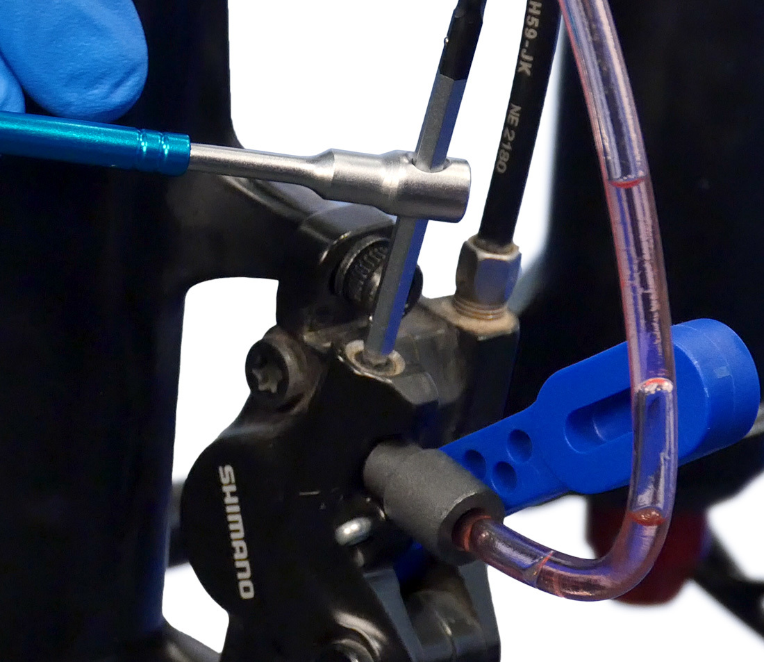
Be sure the bleed funnel is more than half full, then loosen the caliper bleed nipple one half turn. Squeeze the lever gently to start the fluid flow from the bleed funnel down to the caliper and through the hose into the disposal bag. Tap along the length of the hydraulic hose to encourage any bubbles to dislodge.
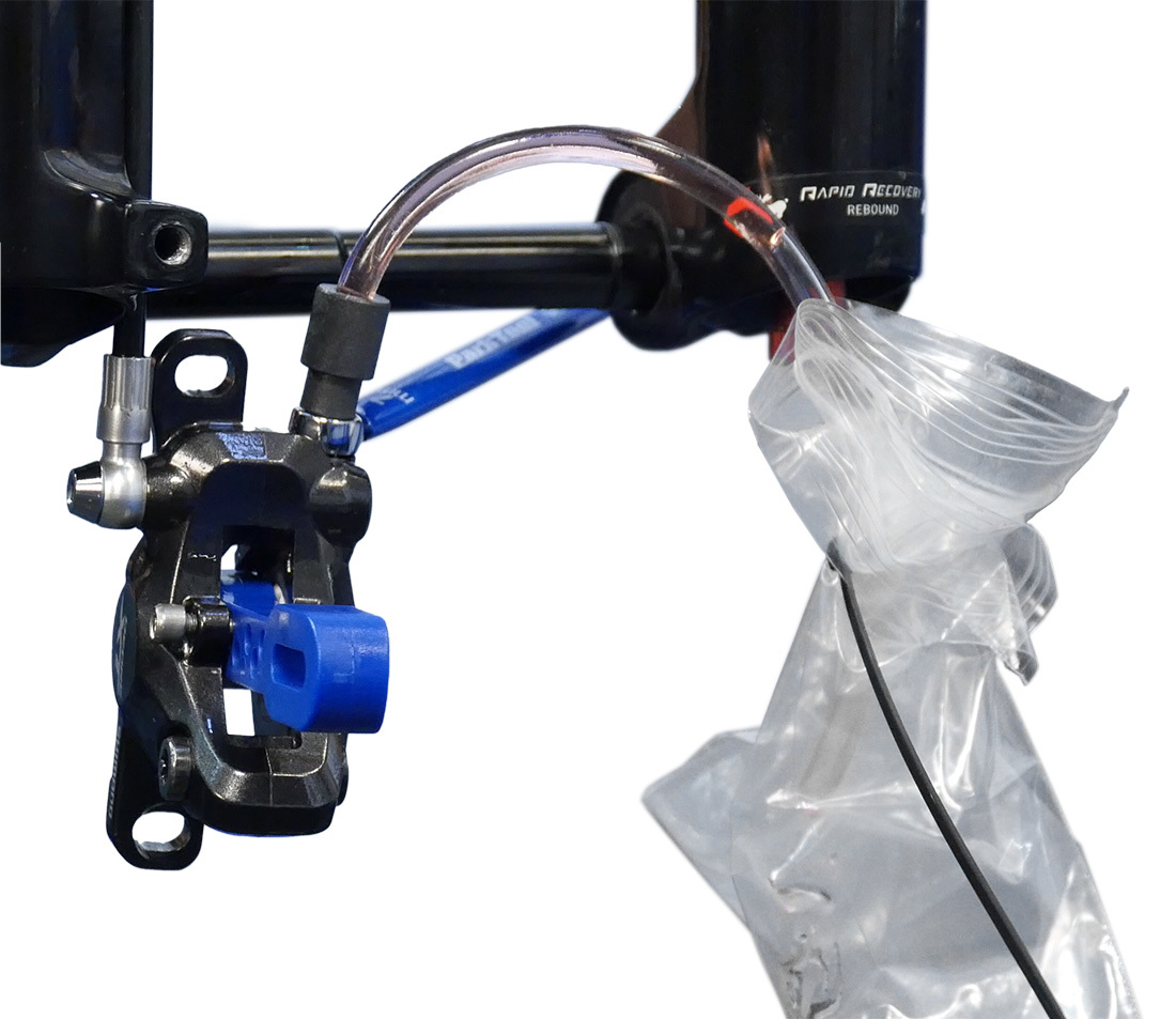
Install the open hose with plastic bag on the caliper bleed port
Tap the hose to eliminate bubbles
Keep an eye on the bleed funnel. Do not let the funnel run out of fluid. Add fluid as necessary to avoid letting air enter the brake lever port.
When no more bubbles appear in the drain hose, close the caliper bleed nipple. NOTE: You may not see bubbles during your bleed.
Leave the funnel and bleed hose in place. If necessary refill the bleed funnel to about half full.
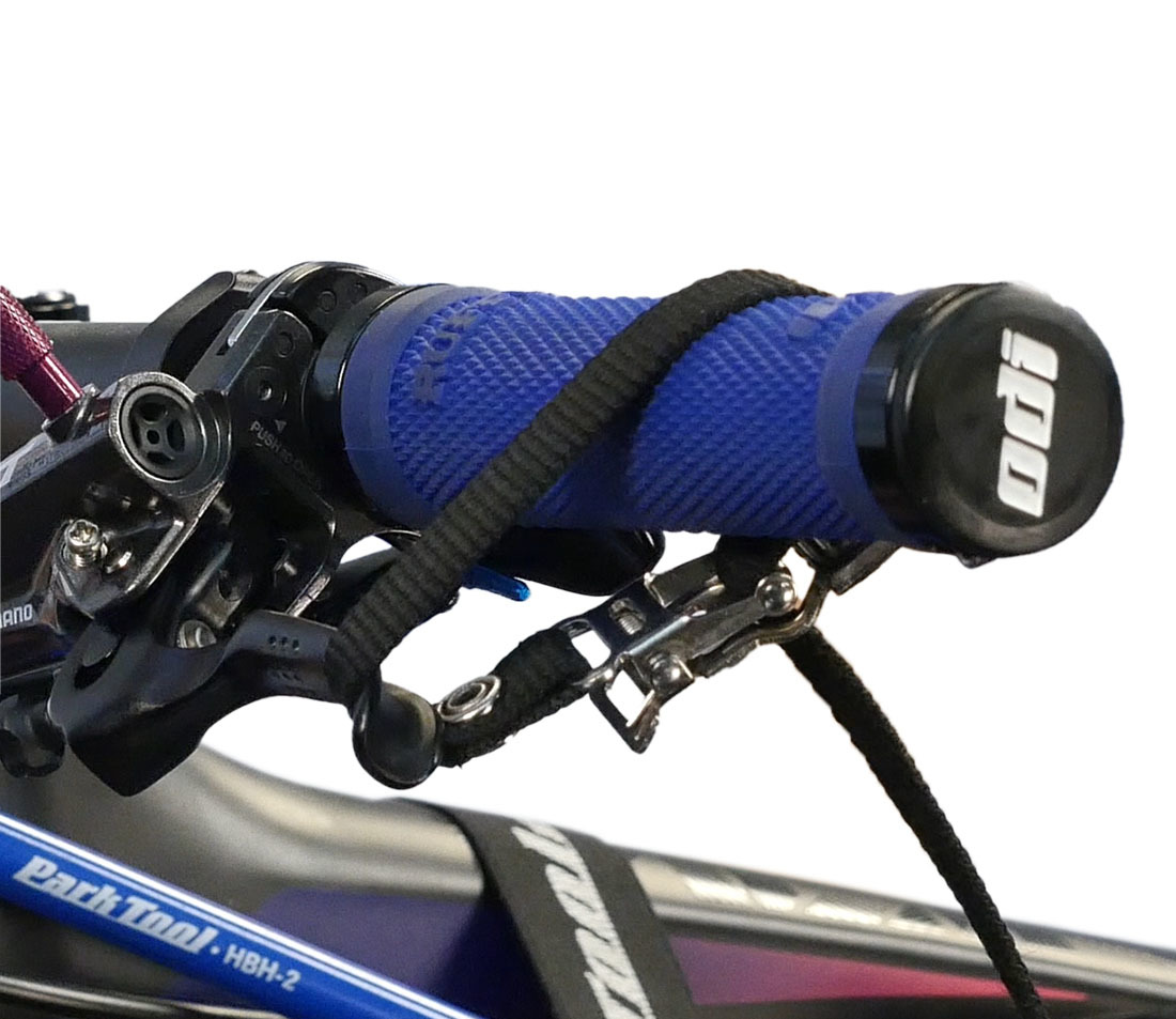
Pull the lever to maintain pressure on the pistons. Hold the lever to the handlebars with a strap or zip tie.
Always ensure that the bleed funnel is at least half full
Quickly open and close the caliper bleed nipple once. Pressure will be lost at the lever as fluid is forced out the nipple. Loosen the strap and re-pump the lever until it feels firm, then re-tighten the strap. Repeat the quick opening and closing of the caliper bleed nipple. Remove the strap from the lever.
The caliper work is done. Remove the bleed hose, tighten the bleed nipple to a torque of about 4-6 Nm and reinstall the caliper bleed cover.
Squeeze the brake lever. It should feel firm now. If not, there is still air in the system — repeat the bleed from the beginning, reassessing your process.
The caliper and brake line should be free of air. However, there can still be bubbles at the lever just below the bleed port.
Rotate the brake lever so the funnel is 30 degrees back from vertical. Squeeze and release the lever a few times while inspecting inside funnel for any bubbles. Then rotate the lever so the funnel is 30 degrees forward of vertical for a second burp positon. Again squeeze and release the lever to clear any remaining air bubbles
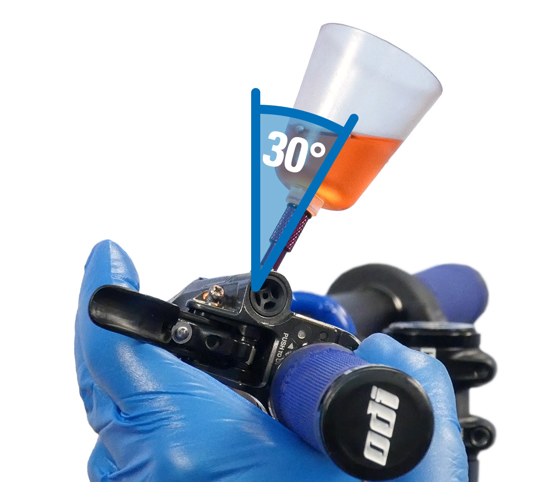
Lever rotated so funnel is 30 degrees back from vertical
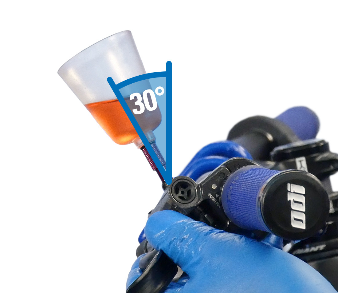
Lever rotated so funnel is 30 degrees forward from vertical
When there are no bubbles appearing from either tilted funnel position, rotate the lever until the funnel is vertical. Plug the funnel, and remove it and the adapter from lever. Always check that the adapter O-ring did not get left behind in the lever.
Install the lever bleed screw with O-ring and secure. It is a mild torque of 1 Nm. Return the lever to riding position and secure. Remember also to return the lever reach and free stroke adjustment to their original settings.
Remove the bleed block and clean the lever and caliper with a rag and alcohol.
If removed, reinstall the brake caliper. Install brake pads.
Reinstall the wheel. Pull the lever repeatedly to bring pads to rotor. Re-center brakes as necessary.
Next article in this series
Hydraulic Disc Brake Alignment View Article
Related articles
Brake Bleeding for Shimano® Drop Bar Hydraulic Brakes Using the BKM-1 View Article
Disc Brake Pad Removal & Installation View Article
Disc Brake Rotor Removal & Installation View Article
Disc Brake Rotor Truing View Article