Post Mount Disc Brake Facing with DT-4
This article will review the use of the DT-4 Disc Mount Post Facing Tool (discontinued).
Getting Started
The DT-4 is a precision cutting tool that will machine the top of the post mounts (direct mounts) to that each is flat and at the same relative height. The DT-4 should be used and stored with care. Components should be kept clean and the facing cutter should be periodically wiped with an oily cloth or rust inhibitor before storage. Store the DT-4 in a safe location.
Determine the required axle size and assemble DT-4. The logo will face the back of the fork or bike. For open dropout front forks, install the 100mm wide axle supplied with the DT-4 (figure 1). For rear open dropout frames of 135mm, install longer axle supplied (figure 2). For bikes with 130mm spacing, simply flex open the dropouts and use the same 135mm axle. This will not damage or bend the frame.
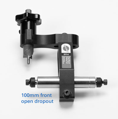
Figure 1. Assembly for 100mm fork with open dropouts
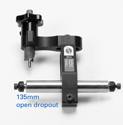
Figure 2. Assembly for 135mm rear open dropouts
For 12mm rear thru axle, use the adapter bushing supplied with the DT-4 (Figure 3). For forks with 15mm thru axles, use the adapter bushing suppied wth the DT-4 (figure 4).
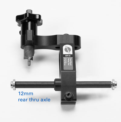
Figure 3. Assembly for 12mm thru axles
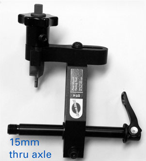
Figure 4. Assembly for 15mm thru axles
For 20mm thru axle forks, no adapter bushing is required (figure 5). Use the axle from the fork.
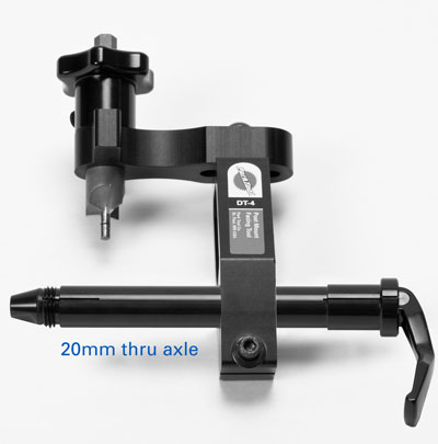
Figure 5. Assembly for 20mm thru axle

Facing
- Install axle of the assembled DT-4 into frame or fork dropouts. For 9mm and 10mm axles, it is important to hold the axle firmly up into drop out and secure axle mounting screws (figure 6). The DT-4 will cut only as accurately as the axle is installed. For 12mm, 15mm and 20mm thru axles, tighten axle mounting bolts, pinch bolts, or quick-release provided with bike.
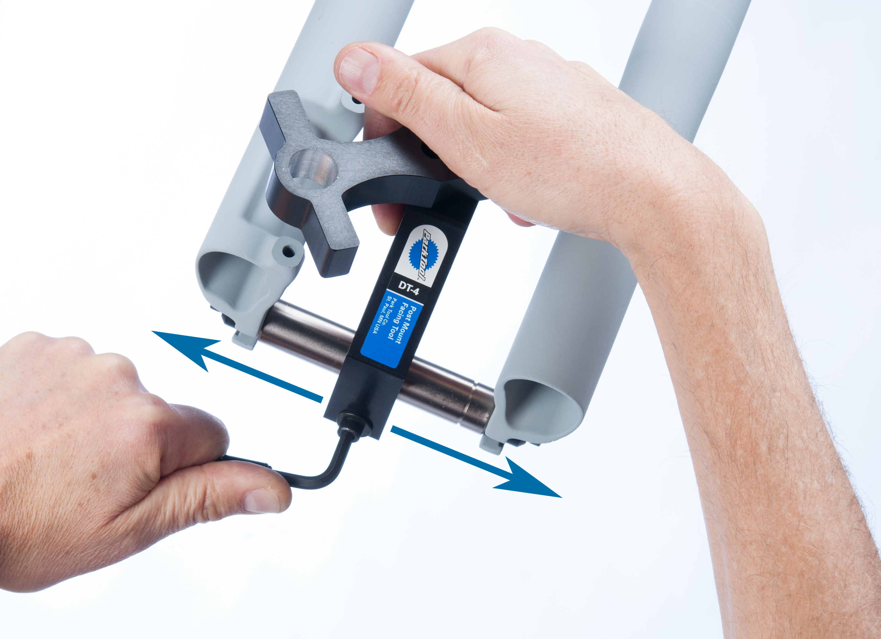
- Slide base of DT-4 laterally on axle until it is approximately centered between dropouts. Base position must allow cutting arm to reach both post mounts. Tighten base screw enough to hold position but still allow base to rotate on axle (figure 7).
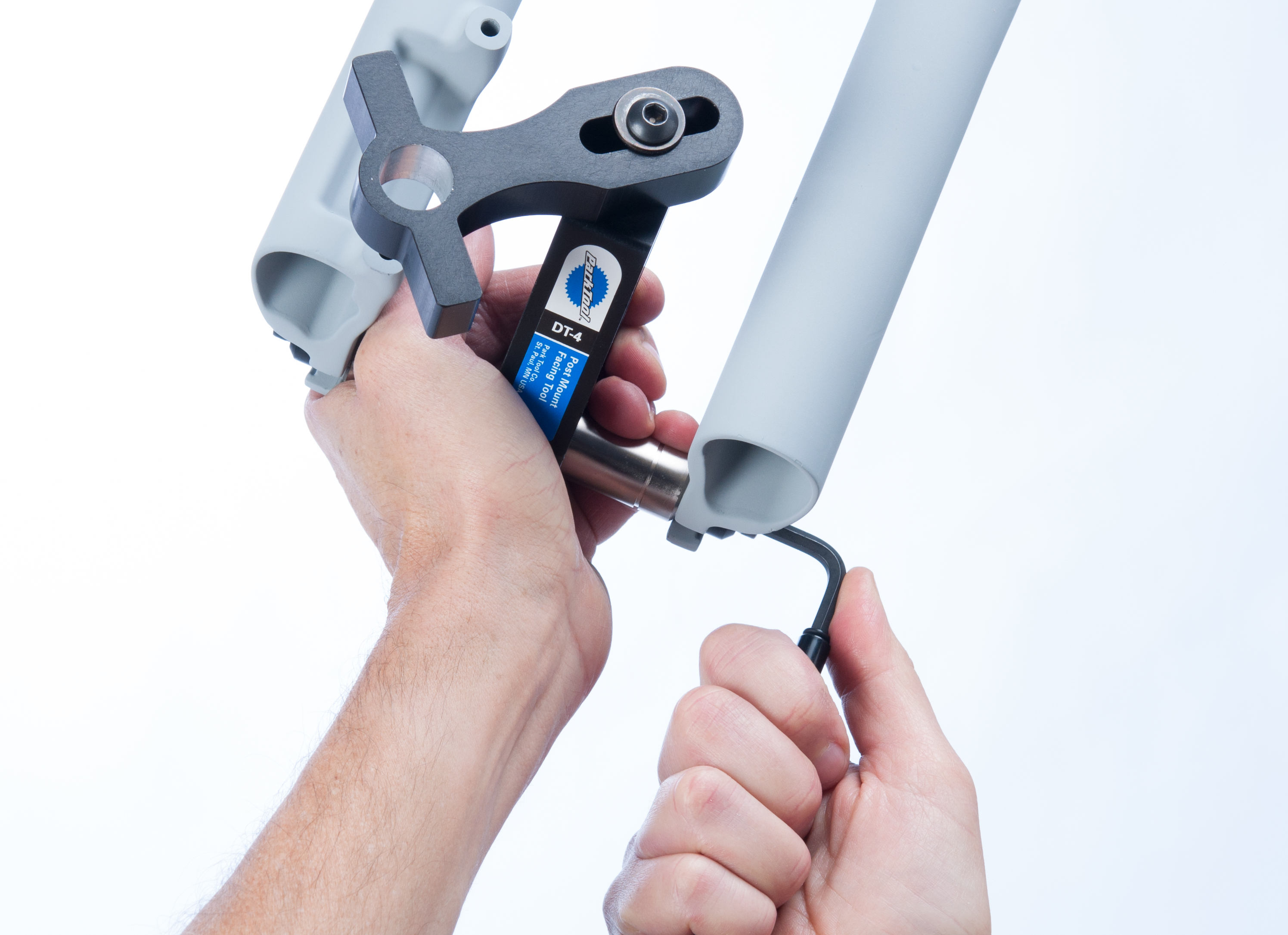
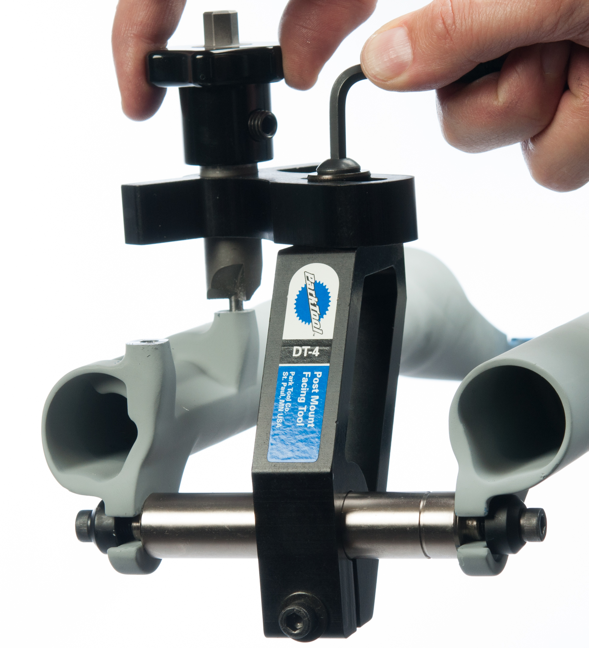
- Rotate cutter arm so wing of cutter arm is positioned directly above the post mounts (figure 8 and 9). Tighten cutter arm screw to lock position. This will allow cutting body to be accurately rotated.
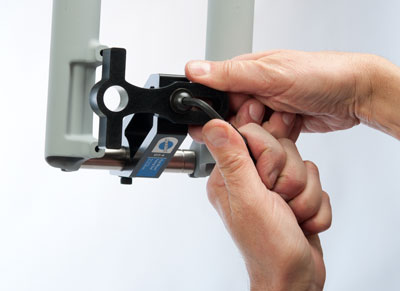
Figure 8. Postion wing of cutter arm over post mounts
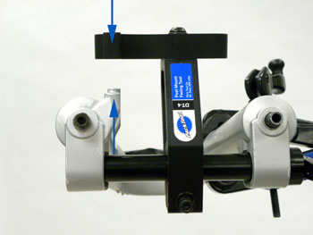
Figure 9. Cutting arm wing over posts for alignment procedure
- There are four different post mount-to-axle standards. To accomodate these standards, the DT-4 includes two parallelism gauges. Each gauge is made of two parts that slide on each other to create a range of sizes. The shorter “L” section of each gauge provides a second range of sizes. Select the parallelism gauge that will expand to fit between the disc brake post mount and the wing of the cutter arm.
- Place appropriate parallelism gauge on top of post mounts. Rotate base and cutter arm until wings of cutter arm are parallel with parallelism gauge. (Figure 10). Tighten base screw to secure position.
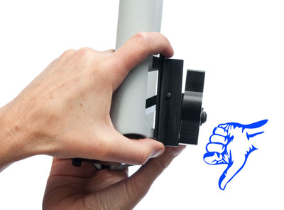
Figure 10a. Poorly rotated cutting arm. Base should be rotated counter-clockwise slightly from this view
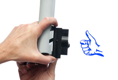
Figure 10b. Correctly rotated cutting arm
- Double check axle security and rotation. Remove parallelism gauge from post mounts.
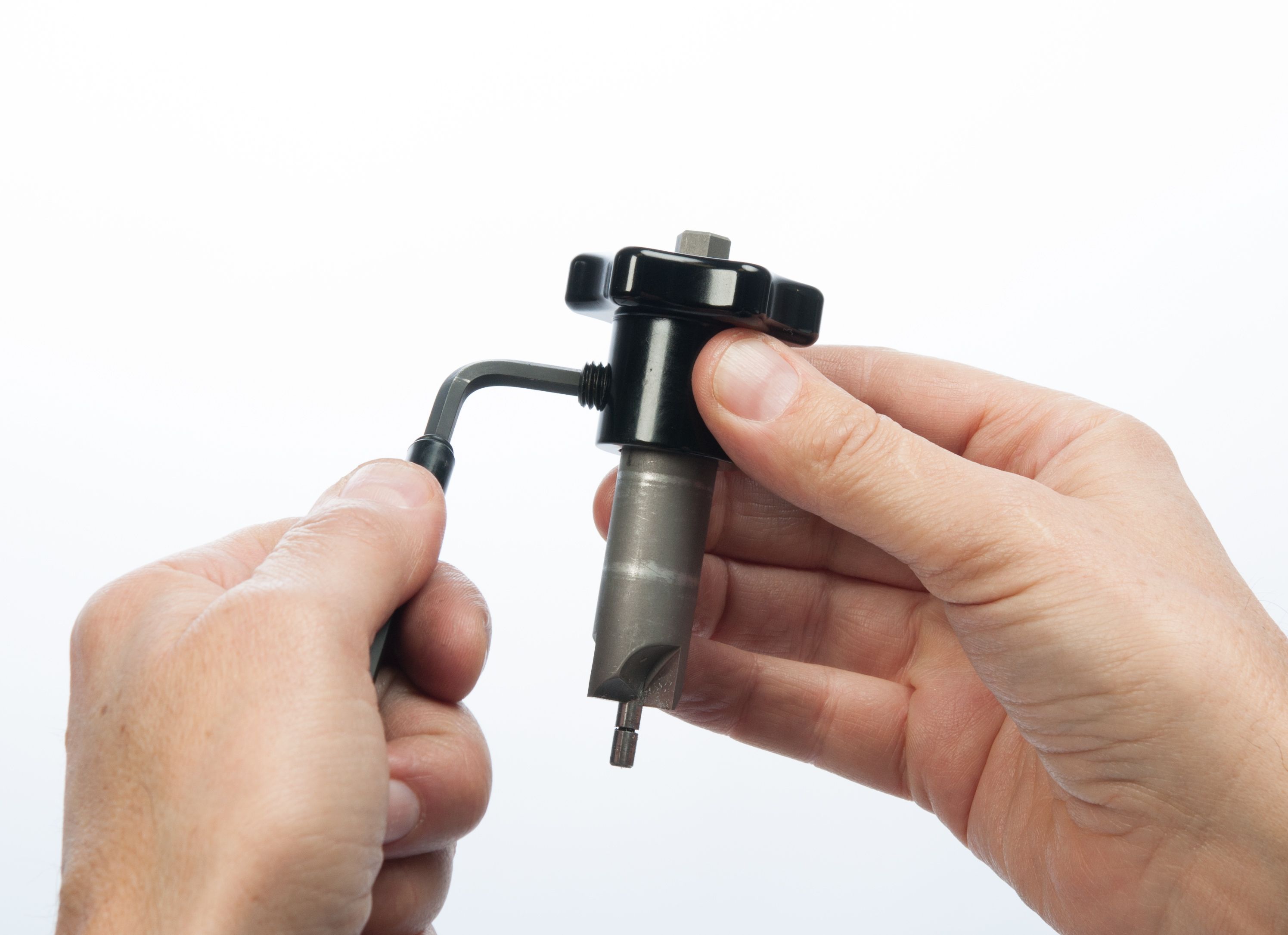
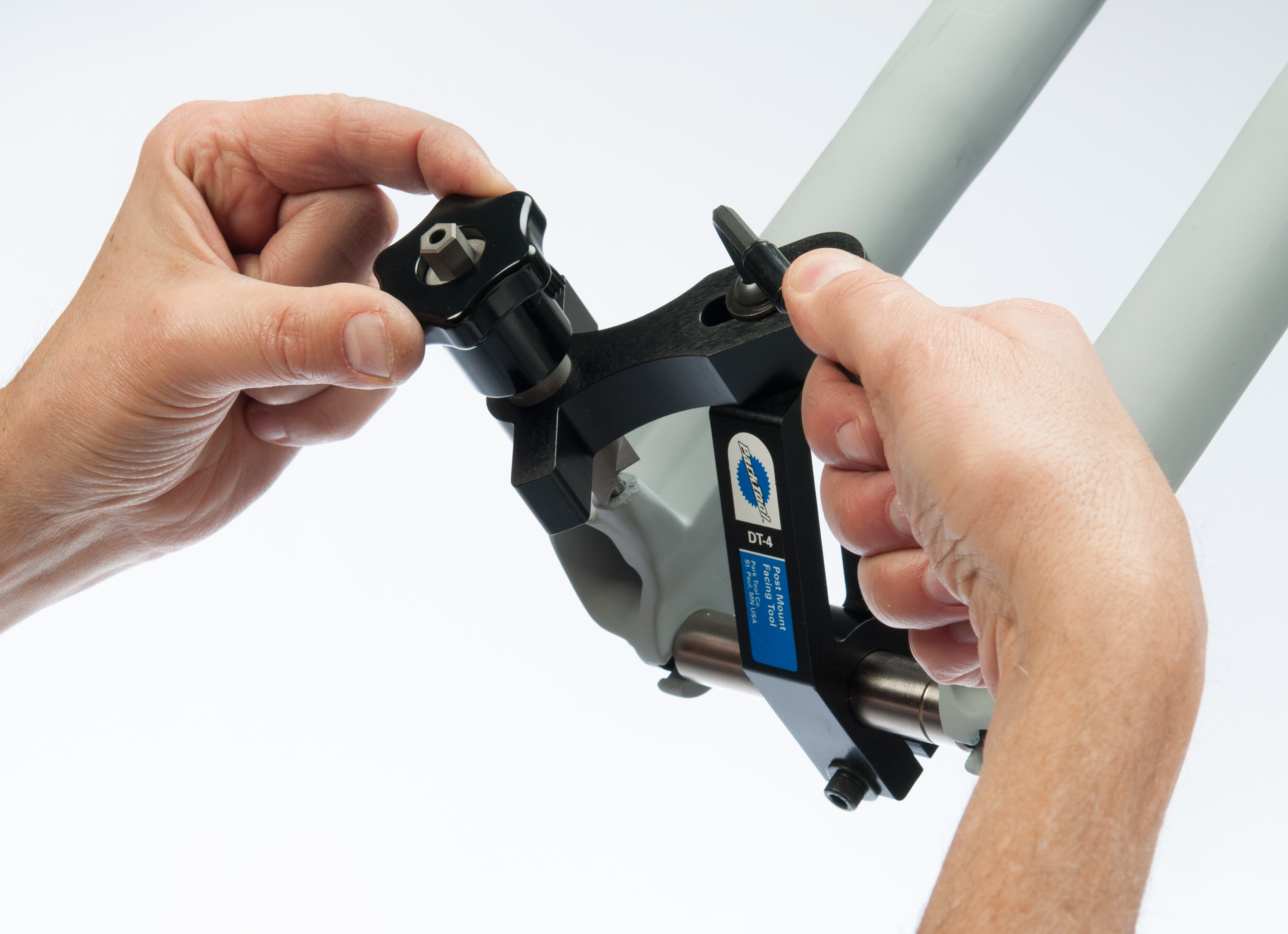
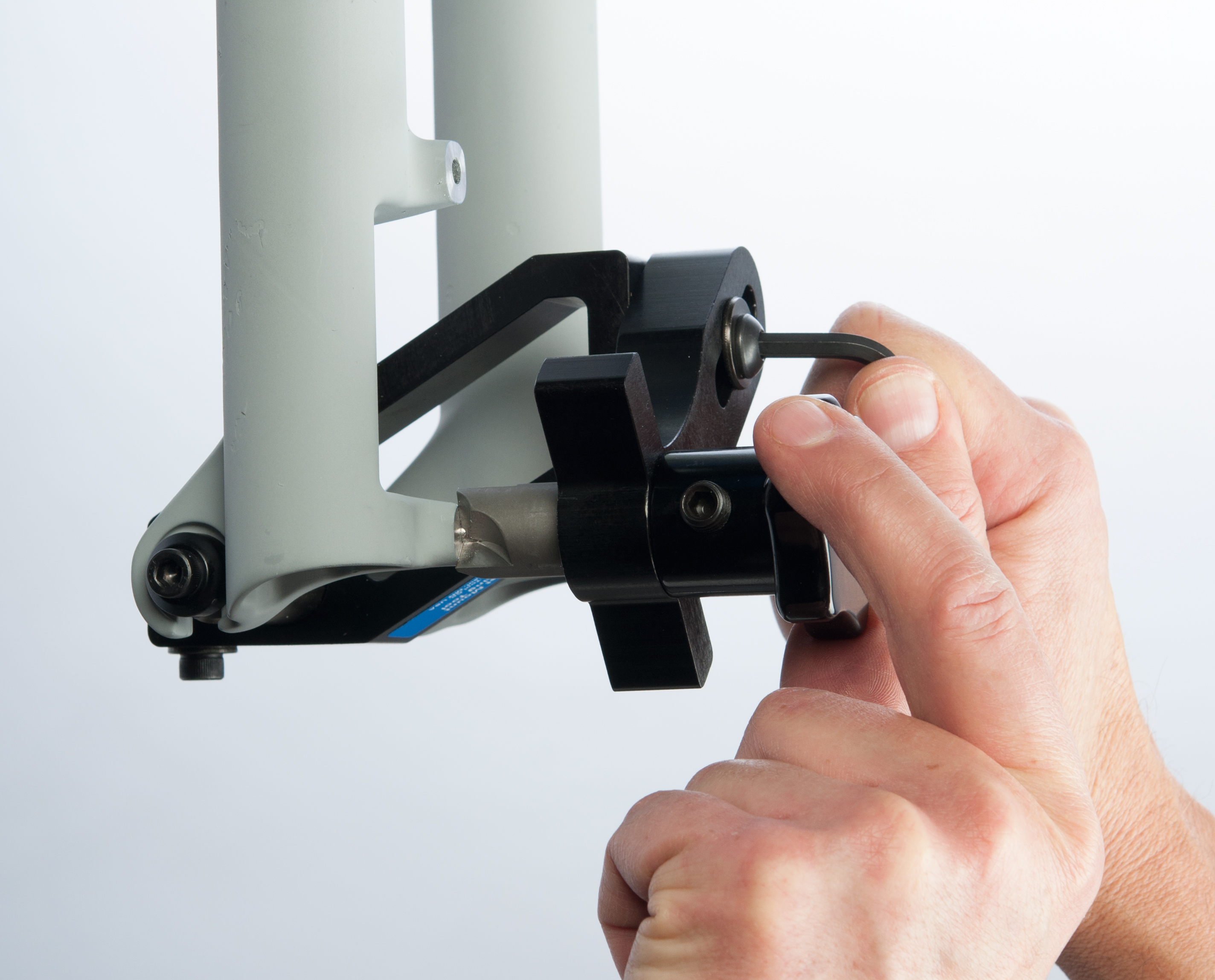
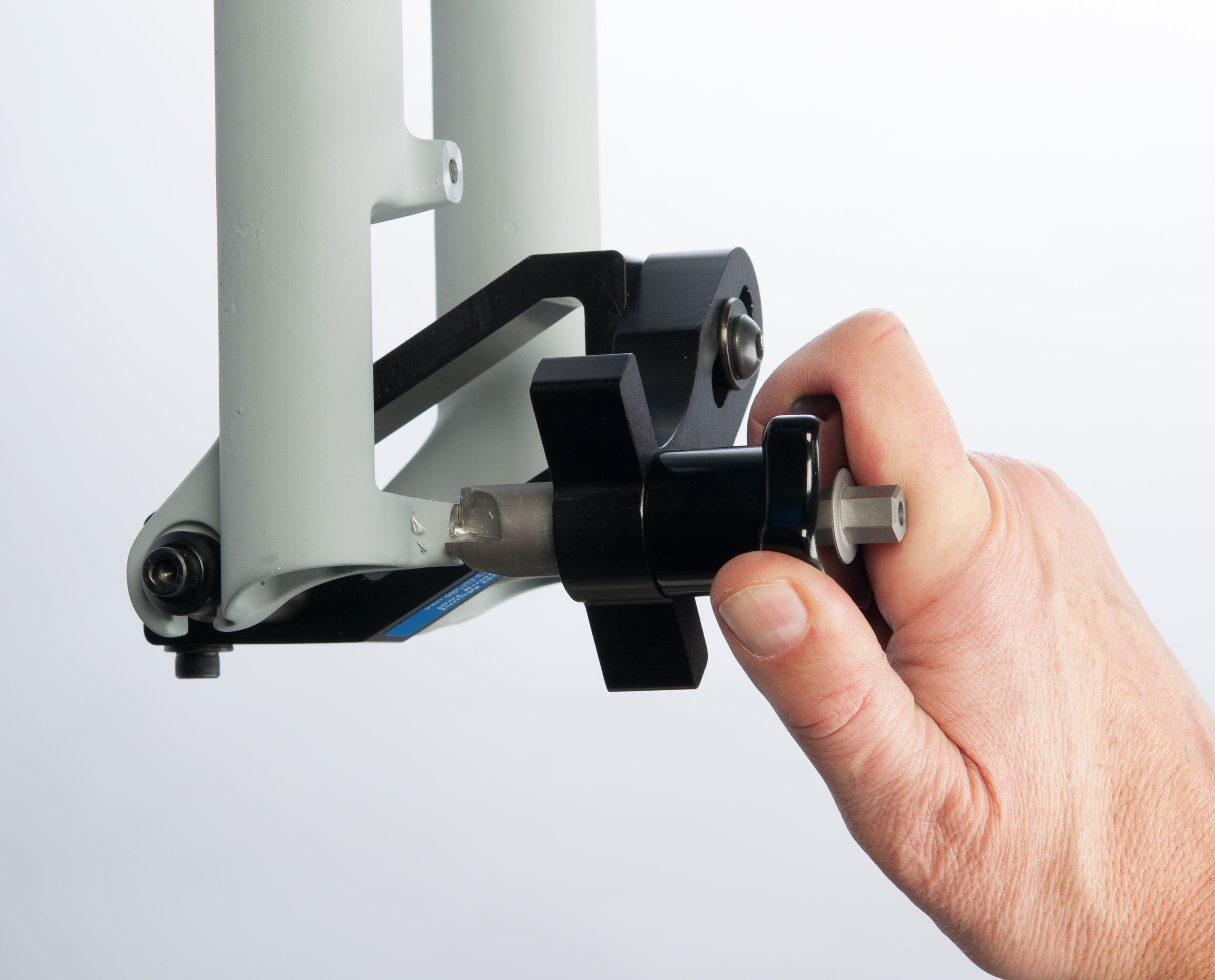
- Set facing cutter near end of knob. Loosen knob setscrew and slide knob to end of facing cutter, near the 10mm hex. Tighten knob setscrew to secure (Figure 11).
- Loosen cutter arm screw. Install facing cutter into cutter arm and insert pilot of facing cutter into hole of lower post mount. Secure cutter arm screw (Figure 12). No cutting should occur with cutter arm screw loose.
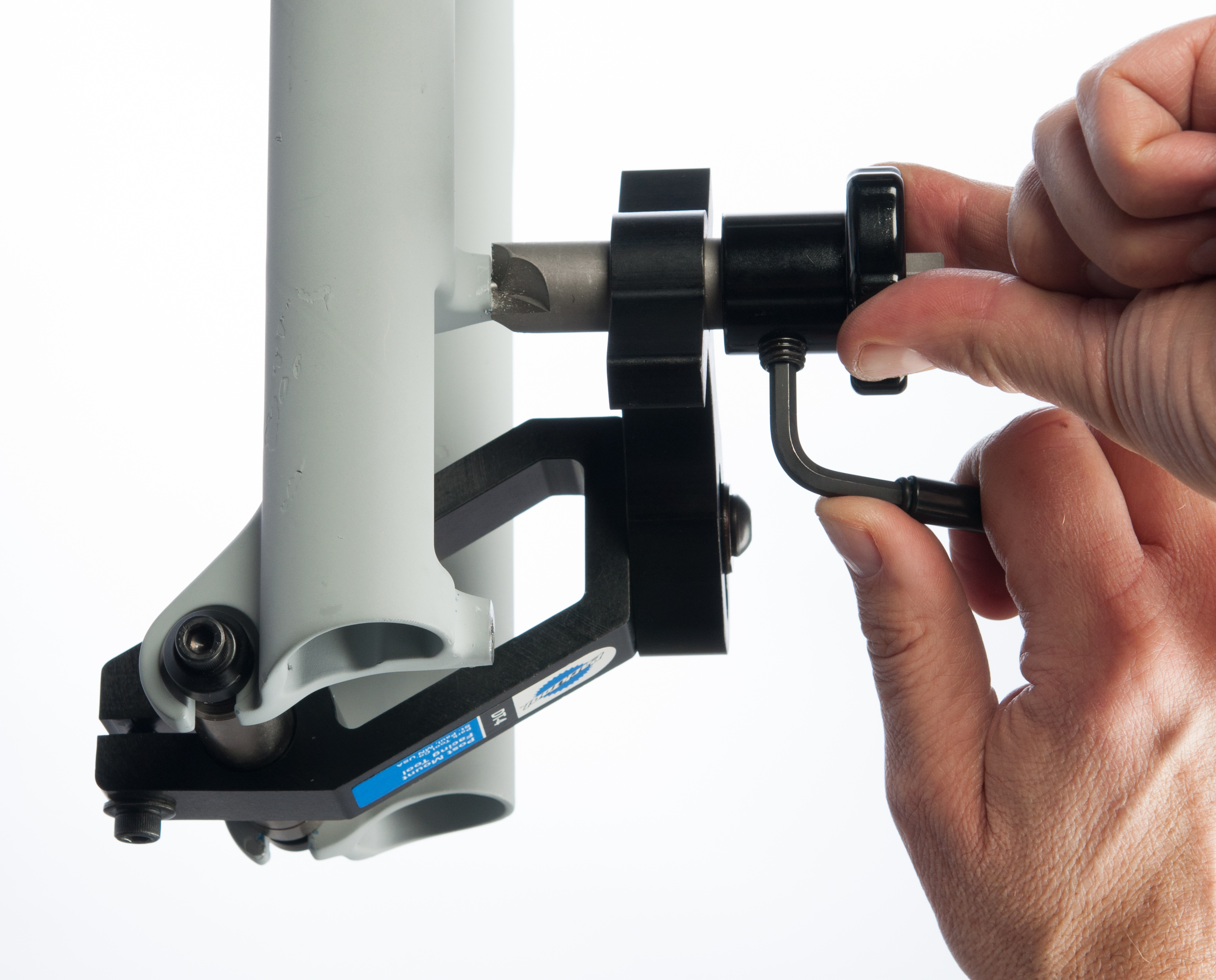
- Turn knob and facing cutter clockwise while applying hand pressure to face post mount (Figure 13). Use appropriate cutting fluid and cut only the minimum necessary for the disc brake caliper body to have a flat secure mounting surface. NOTE: For convenience, use a ratcheting wrench with a 10mm socket to turn the 10mm hex head on the facing cutter.
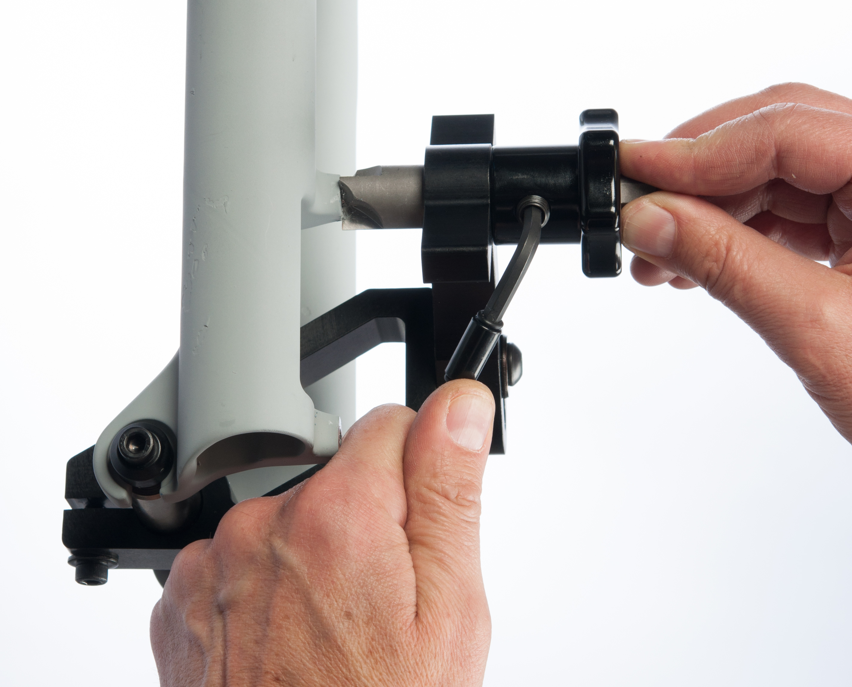
- With teeth of facing cutter contacting face of post mount, loosen knob set screw and slide knob on shaft of facing cutter until knob contacts cutter arm . Tighten set screw. This will set the height of the facing cutter and prevent further cutting (Figure 14).
- Pull facing cutter from lower post mount.
- Loosen cutter arm screw and reposition cutter arm over upper post mount. Reinstall facing cutter into cutter arm and insert pilot of facing cutter into hole of upper post mount. Secure cutter arm screw (Figure 15).
- Note position of facing cutter teeth relative to mount.
- If facing cutter teeth contact the post mount and there is a gap between knob and cutter arm (Figure 16), complete step 14 and stop.
- If knob contacts cutter arm before cutter teeth contact post mount, OR, if knob contacts body at the same time cutter teeth contact post mount (Figure 17), skip step 14 and go straight to steps 15 through 20.
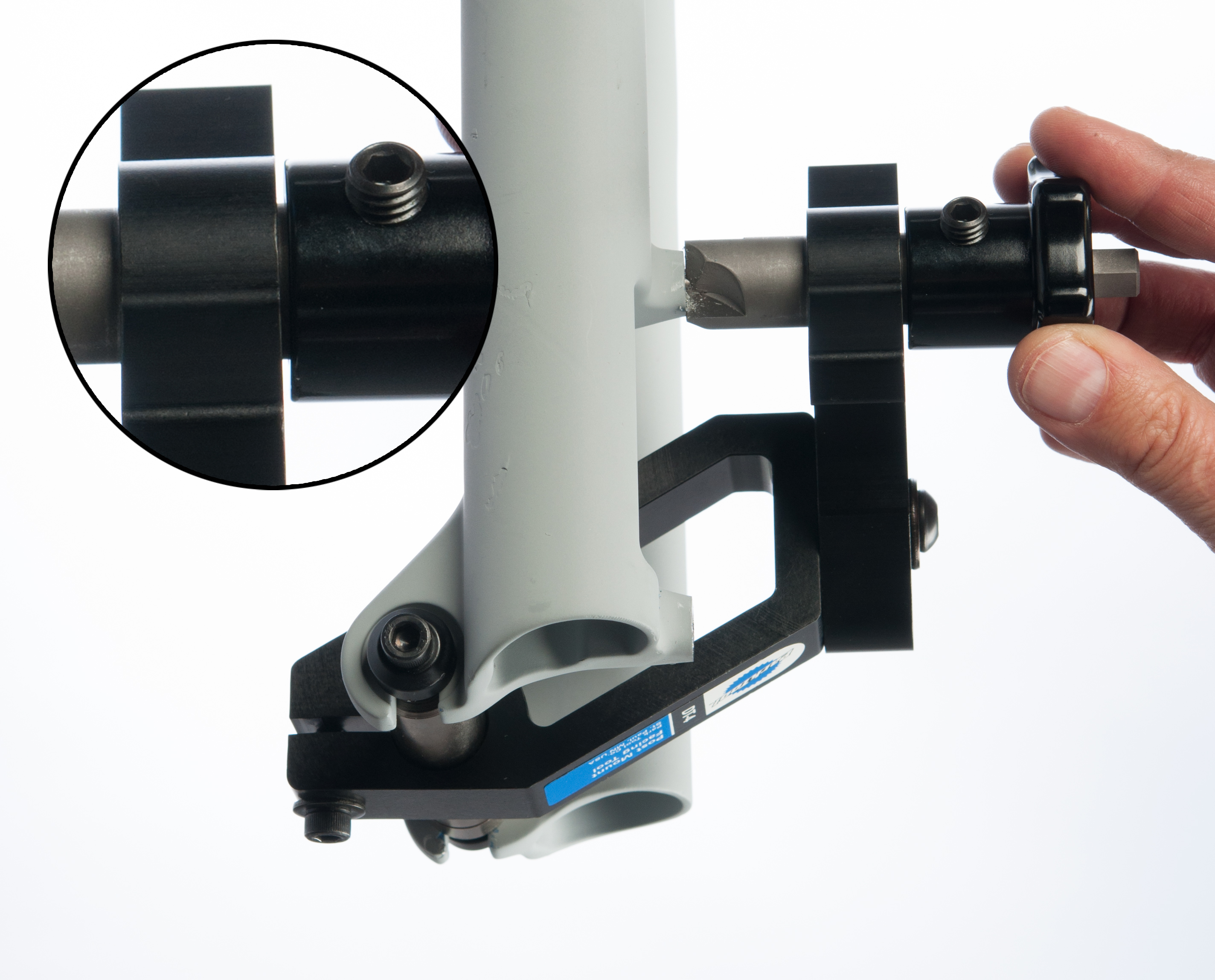
Figure 16. Gap between knob and cutter arm
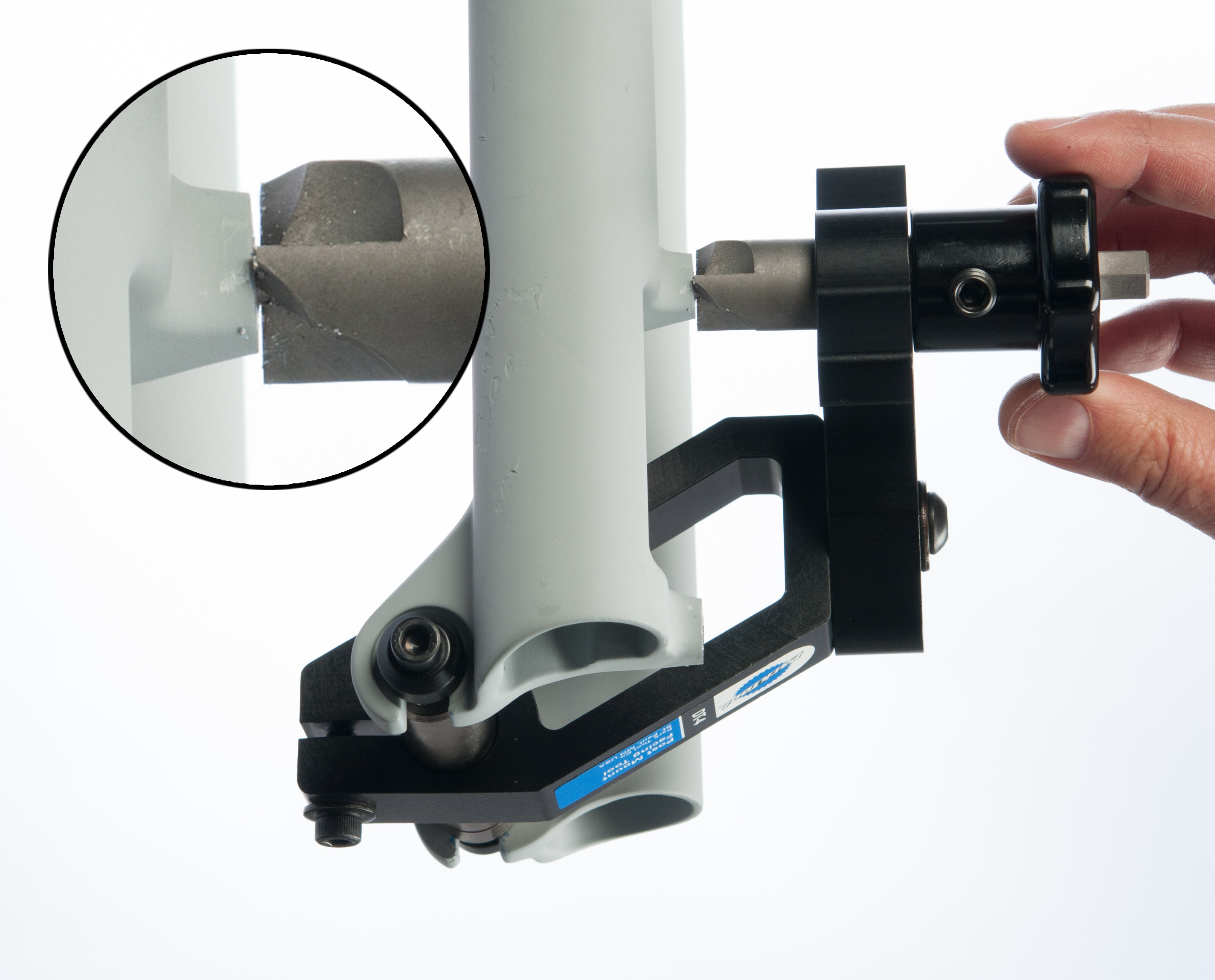
Figure 17. Gap between cutter and post mount
- Turn knob and facing cutter clockwise while applying hand pressure to face surface of post mount. Continue facing mount until knob stops against cutter arm. The facing process is now complete. Remove DT-4 from frame or fork.
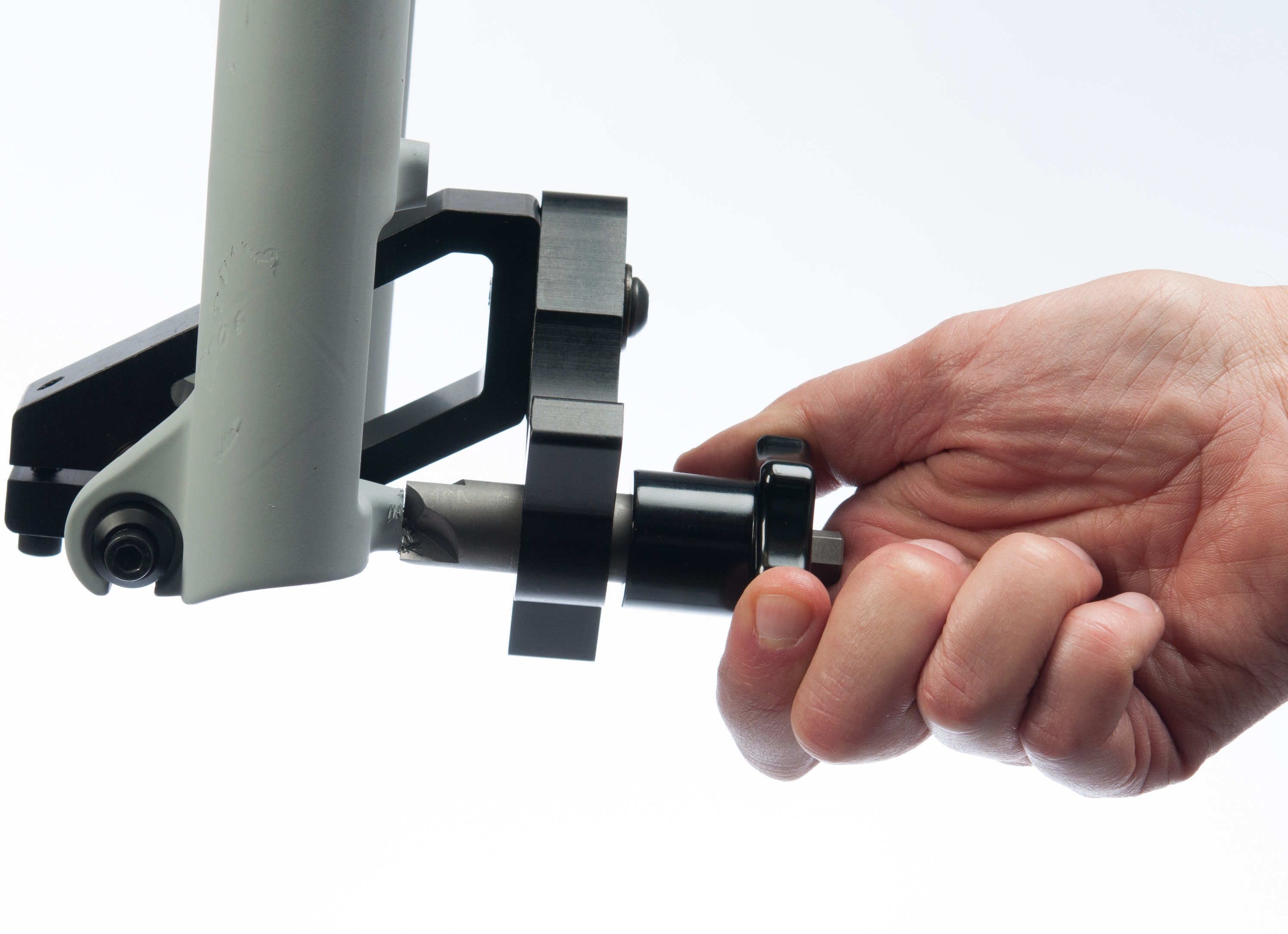
- Loosen knob set screw and position knob at end of facing cutter shaft, next to the 10mm hex (Figure 18). Tighten knob setscrew.
- Turn knob and facing cutter clockwise while applying hand pressure to face surface of post mount. Cut only the minimum necessary for the caliper body to have a flat secure mounting surface.
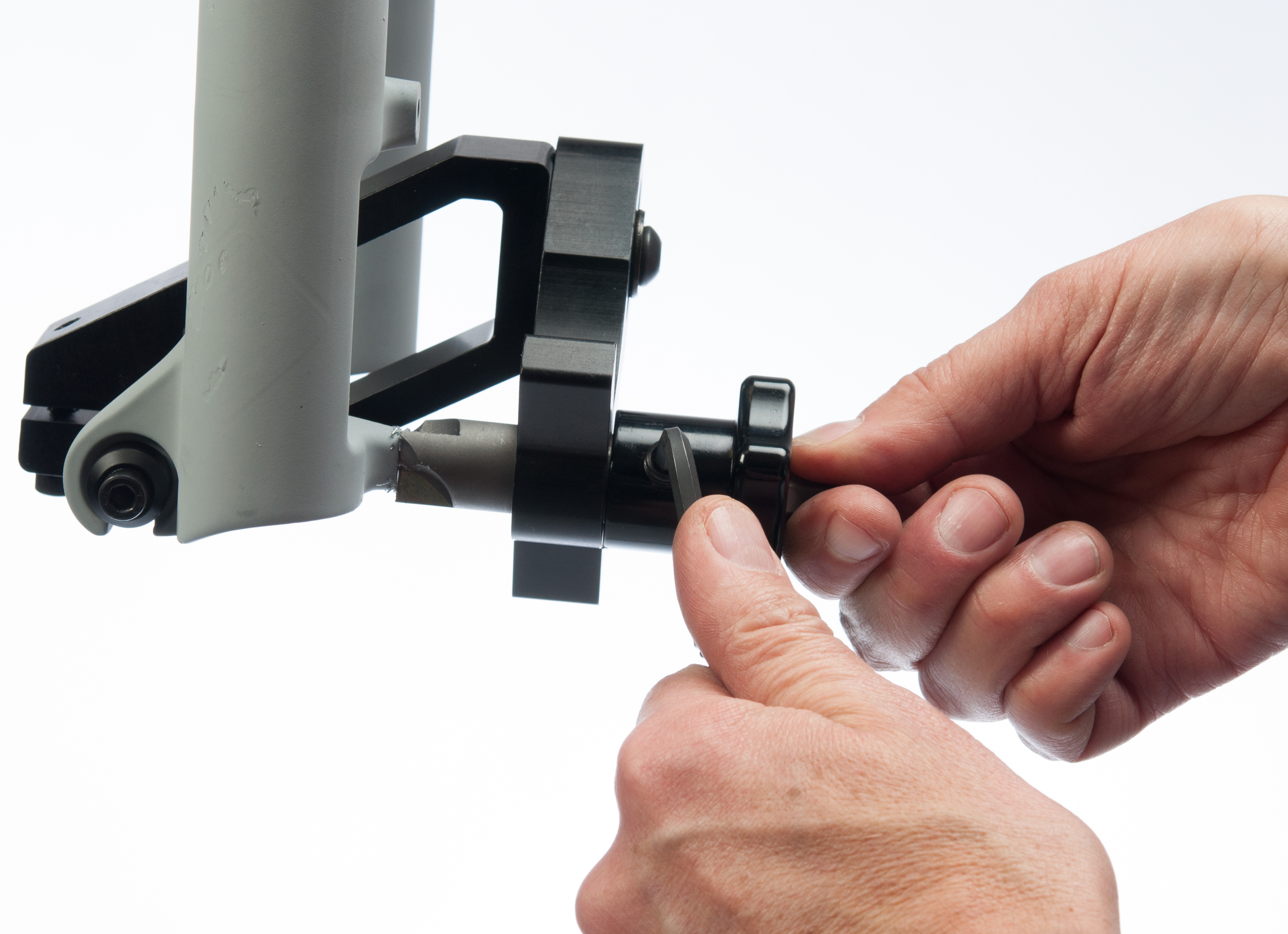
- Loosen knob setscrew and slide knob on shaft of facing cutter until contact is made with cutter arm. Tighten setscrew to secure position (Figure 19).
- Pull facing cutter from upper post.
- Loosen cutter arm screw and reposition cutter arm over lower post mount. Reinstall facing cutter into cutter arm and insert pilot of facing cutter into hole of post mount. Tighten cutter arm screw to secure (Figure 20).
- Turn knob and facing cutter clockwise while applying hand pressure to face surface of post mount. Continue facing mount until knob stops against cutter arm, as seen in Figure 21. The facing process is complete. Remove DT-4 from frame or fork.
- Clean fork of any cutting fluid.