Crank Removal and Installation: Two-Piece Compression Slotted
This article will review removal and installation of two-piece compression slotted cranks such as Shimano® Hollowtech® II.
Getting Started
- Hex Wrench for pinch bolts
- Adjusting Cap Tool (Shimano cranks only):
- Hammer: HMR-4
- UP-SET Utility Pick or SD-3 Flat Blade Screwdriver (Shimano cranks only - for lifting safety plate)
- Torque Wrench
- Thread Preparation:
- Rags

Shimano® Hollowtech® II style crank
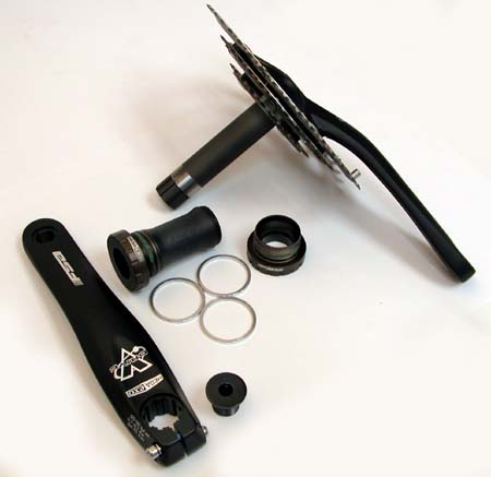
FSA® MegaExo® style crank
Many Shimano® and some FSA® cranksets use a two-piece compression slotted system. These have a left crank arm with a compression slot that is secured by two pinch bolts and a right crank arm with an integrated spindle. These systems use external bearing cups and do not need a conventional crank puller.
The left arms of these crank systems are used to adjust the bottom bracket bearings. Tightening an end cap on the left side pulls the crank arm onto the spindle and against the bearings, much like a threadless headset cap adjusts threadless headset bearings. The left arm pinch bolts are then tightened to secure it and maintain bearing adjustment.
In this repair help article, we will demonstrate how to remove and install this style of two-piece cranksets.
Crank Removal
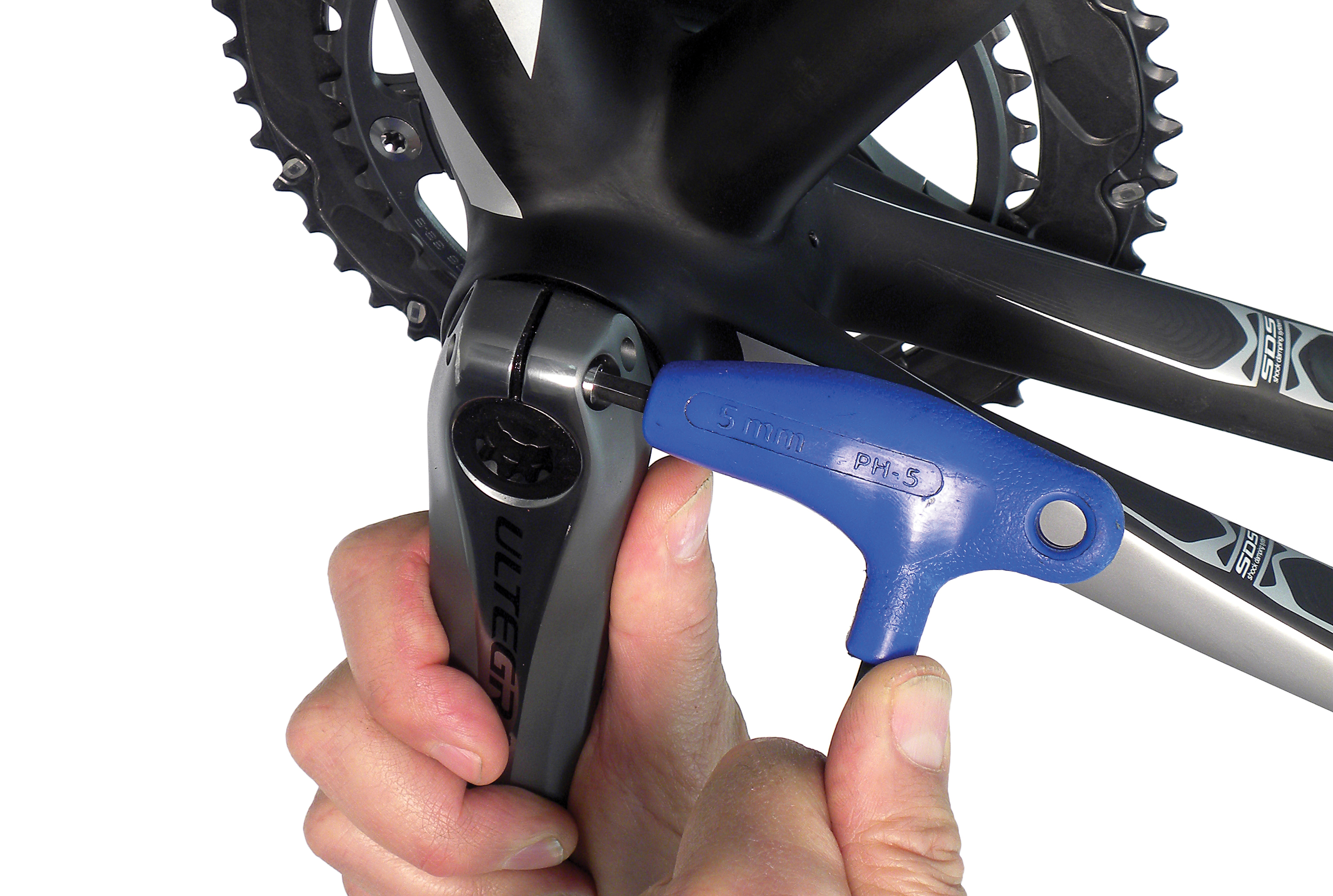
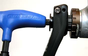
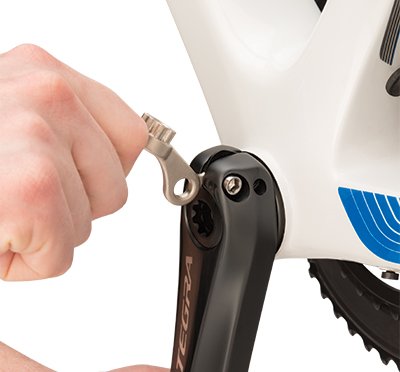
- Fully loosen any pinch bolts on the left side crank.
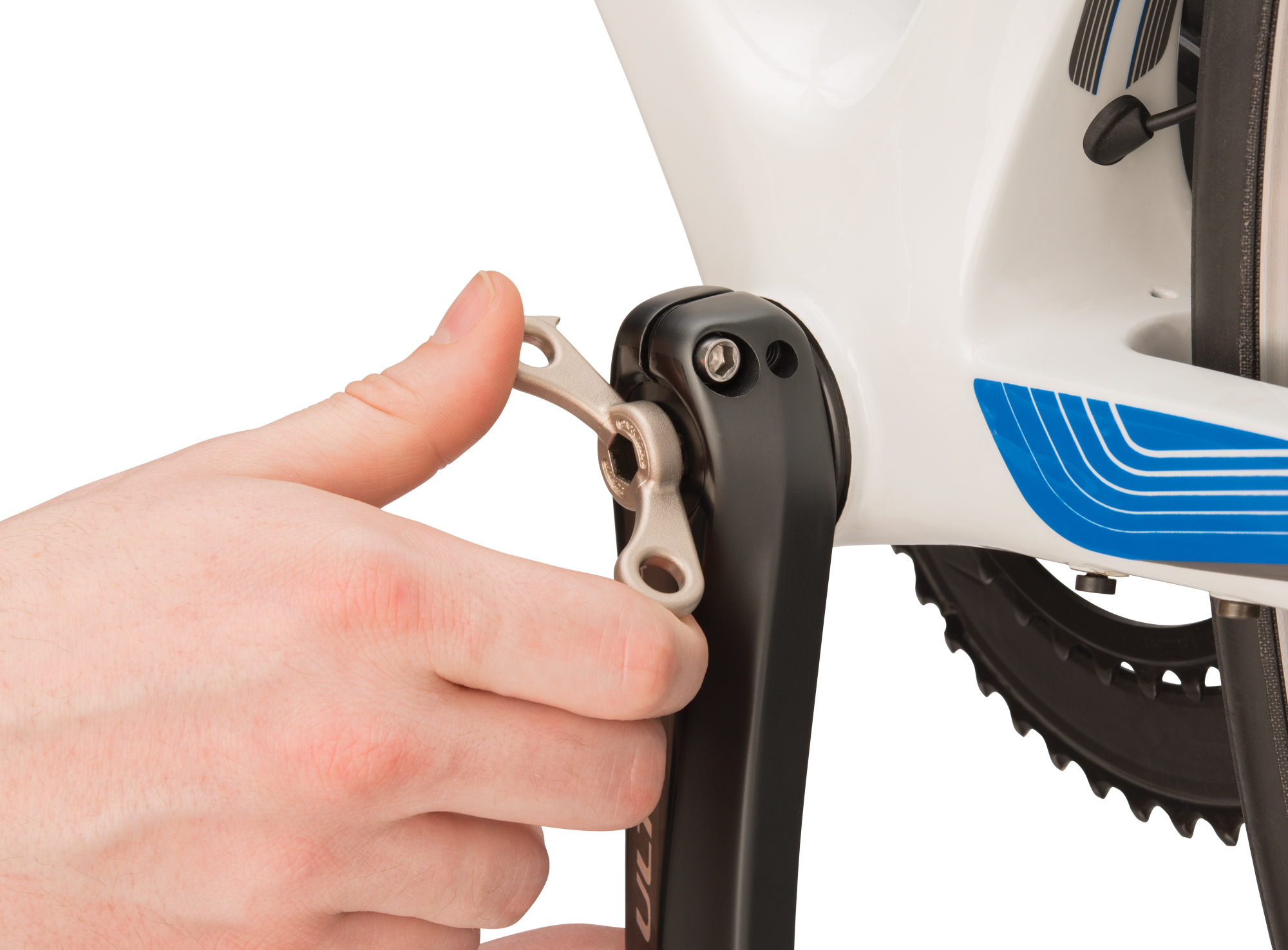
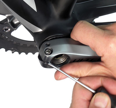
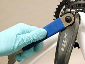
- Turn the left side crank cap counter-clockwise and remove.
- Shimano® cranks use a proprietary eight-pointed star driver. Use the Park Tool BBT-9 or BBT-10.2.
- FSA® crank caps use an 8mm hex wrench.
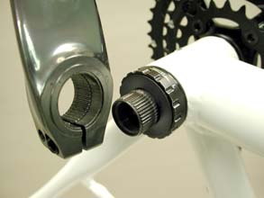
- Pull left arm off spindle by hand. In some cases it may require light tapping with a soft mallet to remove arm if spindle-arm interface is dirty or sticky.
- For Shimano® Hollowtech® II, inspect for a “stop plate” inside the left arm slot. Use a thin screwdriver or integrated hook on the BBT-10.2 to lift this plate upward. The stop plate acts as a safety redundancy to prevent left arm removal. FSA® has no stop plate.
- Remove remaining crank arm by pulling it to the right and out of the bike. It may be necessary to use a mallet to tap the spindle on the left side.
Crank Installation
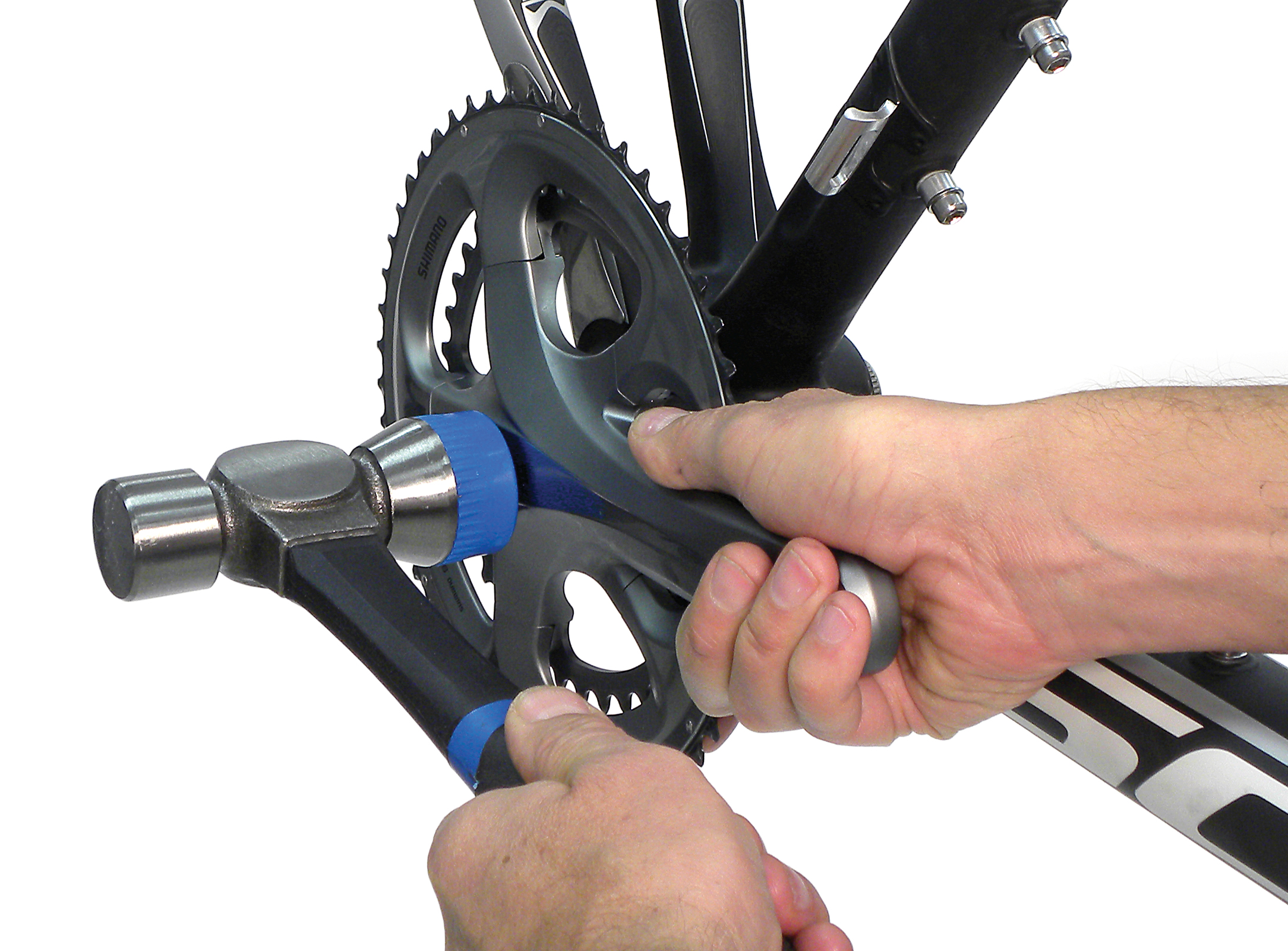
- Grease spindle surface on drive side crank arm and insert it through the right side cup and out the left side cup. The fit is snug, and in some cases gentle use of a mallet may help.
- If spindle appears to catch and will not come out of left side cup, this may be an indication that the bottom bracket shell faces need machining.
- Grease splines of spindle. Apply grease or anti-seize to threads of left arm pinch bolts.
- Position drive side crank arm in the six o’clock position. Hold left side arm in the twelve o’clock position and press arm onto spindle using hand pressure.
- For Shimano® cranks, make sure stop plate is engaged over pinch bolt threads after crank is installed.
- Splines are keyed, and left arm will only install 180 degrees opposite of right arm.
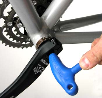
- Apply grease or anti-seize to threads of crank cap and gently thread into spindle. The crank cap pulls the arm toward the bearing.
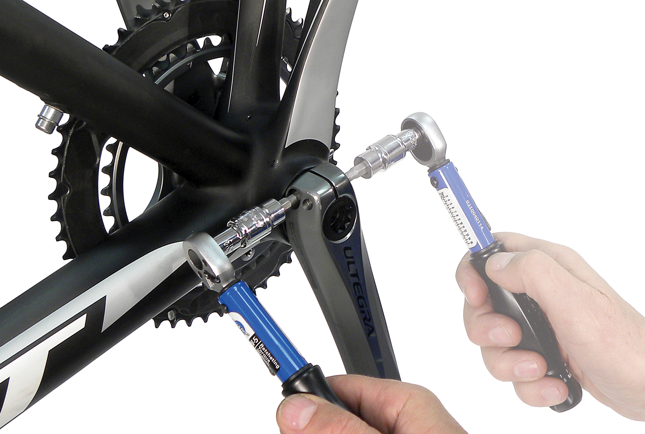
- Tighten the pinch bolts, alternating between them every half-turn to ensure both are fully and evenly tight. Secure to 12 to 15 Nm (88 to 132 inch-lbs). Check arms for play.
Related articles
Crank Removal and Installation: Self-Extracting View Article
Crank Removal and Installation: Three-Piece View Article
Crank Removal and Installation: Campagnolo® Power Torque™ View Article