Bottom Bracket Service: Adjustable Cup-and-Cone
This article will discuss how to service adjustable cup-and-cone style bottom bracket bearings.
Preliminary Info
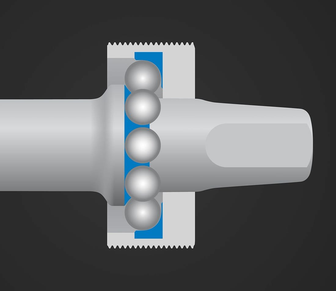
Adjustable style bottom brackets allow for full disassembly, reassembly, and adjustment. There will be a spindle, cups, and ball bearings. The spindle has a cone-shaped race and the threaded bottom bracket cup has an internal cup shape. The bearings are trapped between these.
Disassembly
Begin by removing the cranks. Inspect the non-drive (left) side for a lockring outside the bearing cup. Use a hooked spanner such as the Park Tool HCW-5 to loosen counterclockwise. Remove the ring.
Use the appropriate tool to loosen and remove the non-drive-side cup.
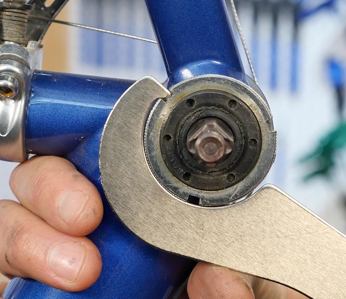
Loosen lockring
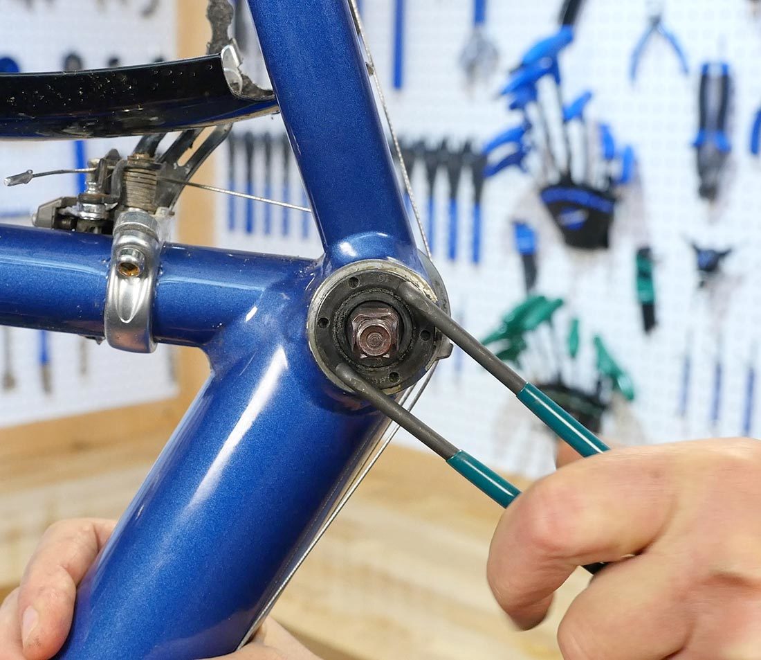
Turn non-drive-side cup counterclockwise to remove
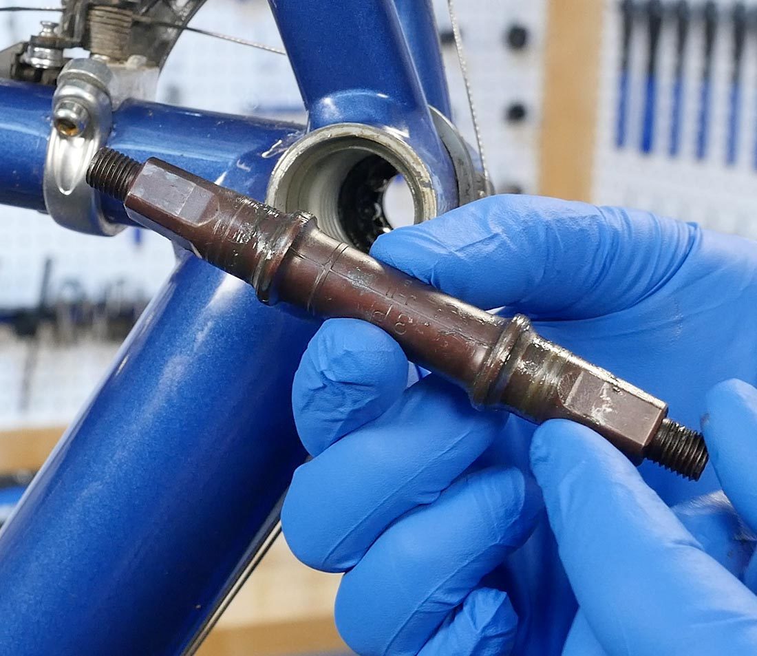
Remove the spindle. As it comes out, note if one side is longer than the other. If the chainrings were adequately positioned, repeat this on reassembly.
Remove the drive-side cup. The wrench flats of the drive side are often very shallow. It is useful to secure the wrench by using a press or threaded rod.
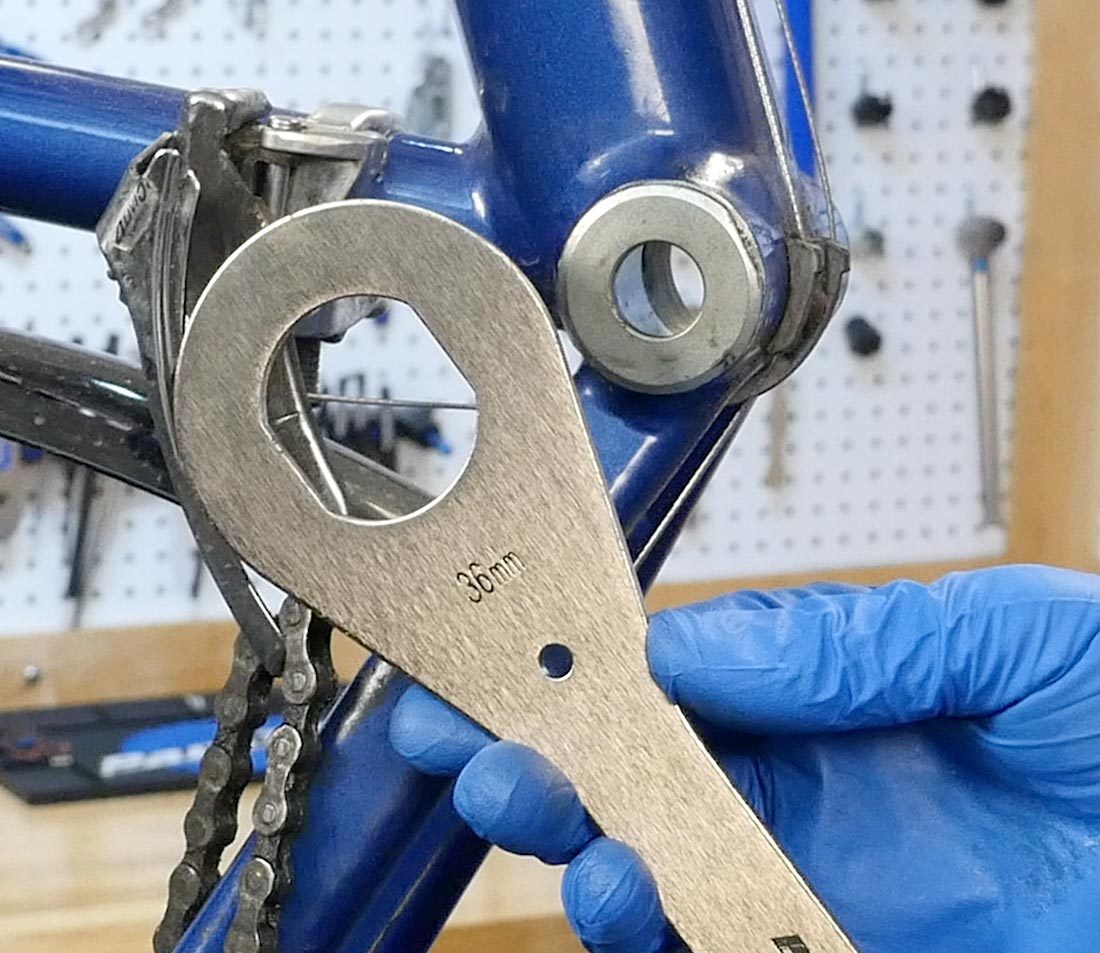
HCW-4 and fixed cup
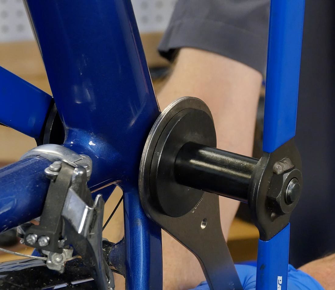
Hold wrench secure using press
Clean all parts and inside the shell with solvent and wipe dry.
Inspect parts for wear. Look at the ball path on both spindle and cups. Trace with a ball point pen. If spindle is pitted it will be felt as ball of pen rolls over pits. Replace bad parts.
Assembly
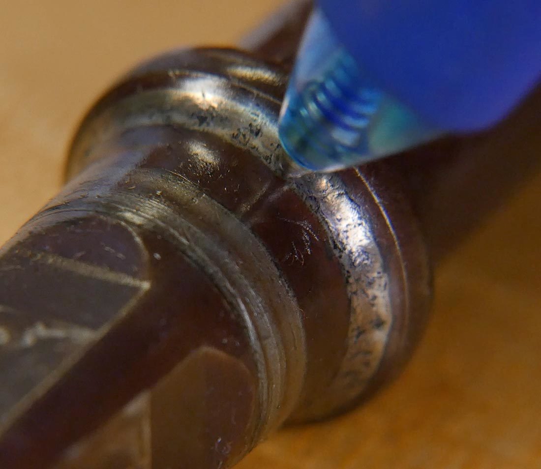
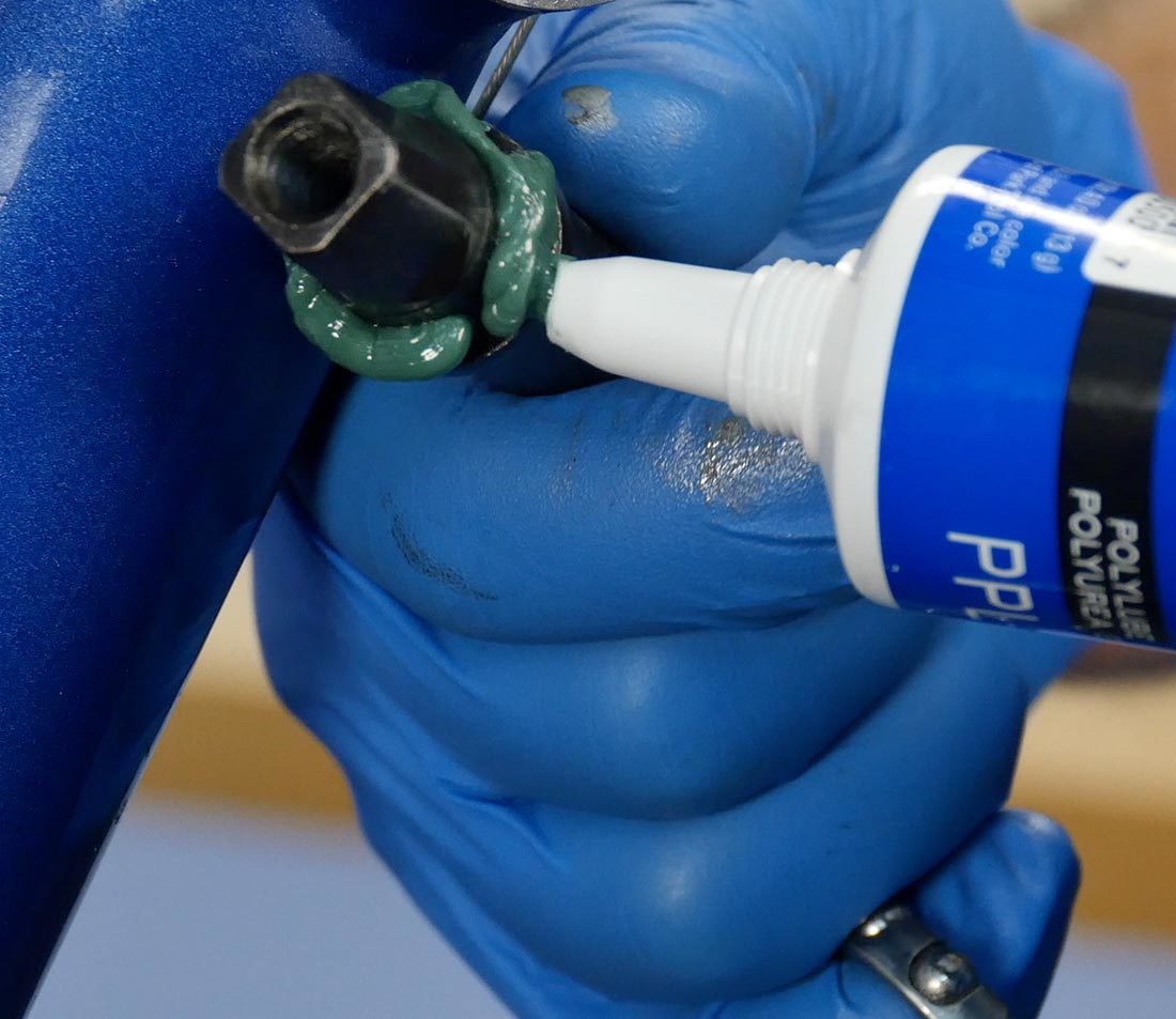
Begin by installing the drive-side cup. Thread preparation for the right side includes a threadlocker such as Park Tool TLR-1. This provides lubrication during tightening and then dries to seal and harden, helping to hold the part.
Another durable option is an anti-seize compound such as Park Tool ASC-1. At a minimum use grease, such as Park Tool PPL-1.
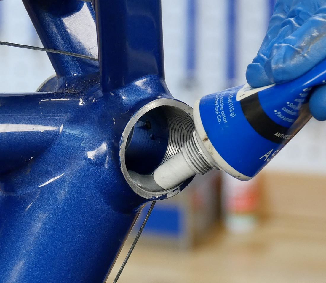
Thread in the right-side cup. For the common English threading, install turning counterclockwise.
Secure the drive-side fully. Use a press to again hold the wrench and secure to an equivalent of 30Nm.
Insert any seal into the bottom bracket.
Grease the spindle heavily and install bearings onto spindle.
Install spindle and bearing through the shell and contact the right-side cup.
Grease inside the left-side cups heavily and install the bearings. Grease the left-side threads and thread in the bearing cup.
Thread the left-side cup into the frame until it just contacts the bearings.
Adjustment
The basic concept for adjustable bearings is to achieve the loosest setting without play. This can be done by purposely beginning with play in the adjustment, then tightening in small increments until play is gone.
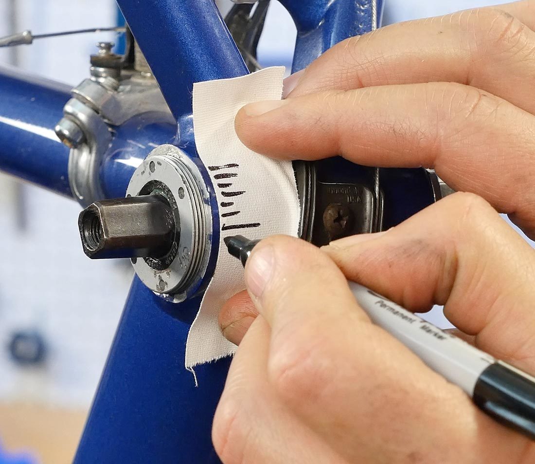
It can be useful to create a reference mark to help control the adjustments to the left-side cup. Place a piece of tape on the perimeter of the shell and make reference lines every 3mm. Make a single line on the cup to track adjustments.
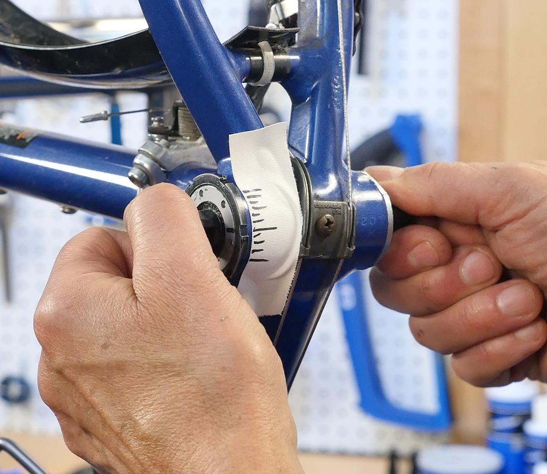
Back out the left cup slightly and then retighten gently until the cup contacts the bearings.
Back off again counterclockwise only a few degrees and install the lockring. Hold the left cup from turning while you fully tighten the locking.

Check for adjustment by grabbing the ends of the spindle and pull up and down on each side. If play or a knocking is felt, make note of the cup reference mark and loosen the lockring.
Move cup tighter by only one incremental reference mark. Hold cup and secure lockring again, then check for play. Repeat the process of checking for play, loosening the lockring, and tightening the cup incrementally until there is no more play.
The right crank can also be mounted to assist in checking play. The arm effectively extends the spindle length and magnifies any play to be more noticeable.
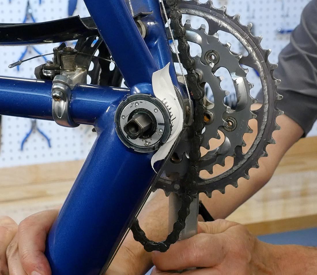
When play is not detected at any point in the rotation of the spindle, the adjustment is done. Remove the tape and wipe off the mark. Install cranks.
Related articles
Bottom Bracket Standards and Terminology View Article