Written by Calvin on January 27, 2012/Calvin's Corner
You Say You Want a (Shifting) Revolution
The Tokheim® Gear Maker shifting system offered a shifting revolution back in 1974, and what a year ’74 was! Cannondale won the Kentucky Derby, Richard Nixon was in office (some of the year anyway), OPEC ended the first oil embargo, Minnesota lost in the Super Bowl, and Huffy put out a yellow bike with Tokhiem shifting. By the way that “Cannondale” was an ungulate, that is a hoofed animal, a horse, not a bike.
Before we take a more in depth view of this now obsolete shifting system, we should pause to appreciate our sample machine and its times (Figure 1). This particular model was made by Huffy in Ohio, USA, and was purchased at the Target Store in St. Paul, Minnesota in 1974. This step-through frame was referred to as a “girl’s bike” or “Ladies bike”.
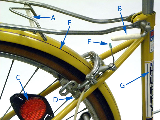 Figure 1
Let us list some of the details of this bike seen in Figure 1:
A: A plastic wrap on the luggage rack to protect the chrome, a subtle and nice touch by the factory.
B: Height adjustment lever, not a quick-release, but a vinyl dipped lever to loosen and tighten the seat post binder.
C: Early clip on reflectors, as required by the newly created (1972) Consumer Product Safety Commission (CPSC).
D: Rear brake arms had a plastic covered support bolted to the pads. This was intended to act as a brace should the flexible caliper (and potentially loose pivot adjustment) move so much that the arms would strike the frame. It is rather a pathetic solution.
E: The color, possibly more then anything, screams 1970’s. We can just see this version of yellow on a Plymouth Duster, or possibly a refrigerator. But as a nice finishing detail note the purple pin strip, done by hand at the factory in Ohio.
F: The original plastic cable end caps are still in place front and rear.
G: Huffy, made in Ohio. Clearly, not a “high performance” bicycle. However, by the late 1980’s, Huffy did offer custom carbon fiber, an idea ahead of its time.
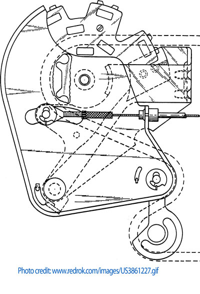 Figure 2. The Tokheim shifting system patent drawing
The Tokheim Gear Maker received a U.S. patent, under the name of Mr. Guilbert M. Hunt in 1972 (Figure 2). It was the creation of Tokheim Corporation while the company was in Fort Wayne, Indiana. Shifting is achieved through changing the rear driving sprocket size by lifting the chain by a series of studs. The effective diameter would increase and lower the gearing.
In the early 70s we were entering a “bike boom” and the multi-geared bikes available tended to be the internal geared 3-speeds from Shimano and Sturmey-Archer. The derailleur shifting systems available then were made in both Japan and Europe. The Tokheim shifting system was an attempt to capture some of inexpensive cycling market. It has not been made in years, and finding parts will be near impossible. Tokheim is still is business, but as a fuel pump manufacturer.
I had my first view of this system at Park Tool just recently. It was on a donation bike to Free Bikes For Kids program, and included a letter written to the family that purchased the bike from the Sporting Good Buyer of Target. Thankfully the little elves at Fb4K did not send it out the door to an unsuspecting youth. The system looks more than capable of hurting anyone working on it.
Looking deeper into the Internet, we can find a Popular Mechanics Magazine article in 1972 by Eugene A. Sloane, in his monthly column, “The Bicycle Shop”. Mr. J. E. Halpin of Cleamson, South Carolina wrote to Mr. Sloan this enquiry: “I recently heard that a revolutionary new gearshift for bicycles has been invented and may be on bikes in a year or two. Can you tell me how this works?” Mr. Sloane answers: “The Tokheim Co, Fort Wayne, Ind,. has announced a new bicycle transmission system with revolutionary aspects. Watch this column for more information on this development.”
It appears that now after 30 years of waiting, we can assume this particular revolution did not, as they say, get traction. However, if you are of a mechanical bent, you may find it an interesting design. Mr. Sloane did not appear to print more on this system, so I will follow up, having missed the revolution the first time.
TOKHEIM SHIFTING SYSTEM
In this system the chain is not derailed in the sense that occurs on the multi-cog shifting bikes. Rather, the chain is lifted up and away from the hub to one of four possible diameters. The chain does not move sideways over different cogs to do this. A series of blocks called “drive segments” can be moved in and out of a rotating plate or disc by the shifting mechanism. A twist grip shifter has five possible detentions. The fifth gear is a regular sprocket, and the other four gears use the block system. This mechanism to accomplish this was called the “interposer”, a great technical term in its own right.
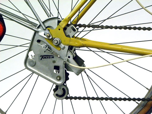 Figure 3. Interposer carrier plate of the Tokheim system
A large disc containing the drive segments rotates with the 12 tooth sprocket. The shifting is done by the cam lever moving these drive segments in or out of the disc (Figure 4). Moving the drive segment out of the disc and into the path of the chain will lift the chain up. Moving the drive segment back into the disc will allow the chain to fall back down to a smaller effective cog size.
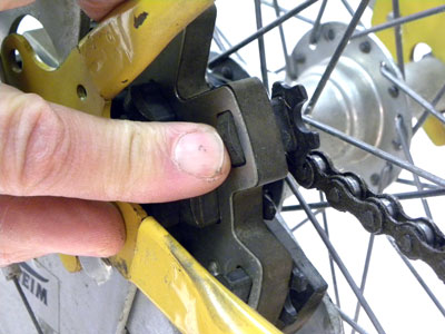 Figure 4. A drive-segment pushed to shifting position
The video below reviews the disc, drive segments and interposer:
There are five gear combinations possible (Figure 5). The 5th gear is the 12 tooth cog and is the highest gearing. This cog has a “skipped tooth” appearance, and these gaps give the 4th gear drive segments a place to sit. The 4th gear drive segments are equal to the size of a 16 toothed cog. The next set of drive-segments, 3rd gear, move the chain outward to what would be equal to a 21 tooth cog. Another twist of the wrist and you are in 2nd gear, effectively a 28-tooth cog diameter, and for 1st gear, the drive-segments are the same diameter as a 34-tooth gear cog.
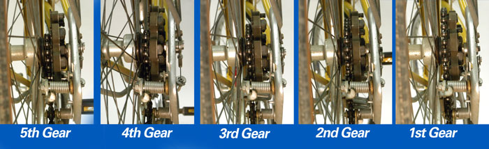 Figure 5. The progression of effective sprocket diameter from the 5th gear (12t) to 1st gear (34t)
If a bike were to have the same gear ratios and use the traditional multiple sprocket freewheel, you would have a 12-16-21-28-34. If there were a freewheel, these would be huge jumps between gears. However, for the Tokheim system, there is no “gear grinding” or slipping between shift. If you watch how your modern hyperglide systems shift, the chain will be engage on two cogs at the same time, and the Tokhiem offered this years ahead.
The shifting action is reviewed in the video below:
The Tokheim instructions are scribed in a style typical of the period. Line drawings were common. What is of interest to me what the orientation of the parts in the instructions (Figure 6). Notice the bike is upside down, which was the common way to work on bikes. The very early repair stands were short and this was because the assumption was the bike was turned upside down, bringing the components up in front of the mechanics.
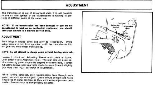 Figure 6. Instructions from the Tokheim Five-Speed Transmission
Working upside down can still be the best method for certain bikes, this being just one example. Imagine a flat tire on this machine, or a worn out tire. The shifting interposer cannot be remove without removing the chain. You must also undo the special clip holding the cable stop. The rear wheel is heavy, and the process is simply a pain. Some electrical bikes are also best serviced in this manner.
Begin by turning the bike upside down. Loosen both side axle nuts. Slide the wheel forward and out of the dropouts. Allow the wheel to rest on dropouts in front of the mounting slot. Deflate the tube and use tire levers to pull the left side tire bead (non-drive side). Work the left bead off the tire while the tire is still in the frame. Seems odd but trust me here. Now work the tube out and snake it past the left side axle (Figure 7).
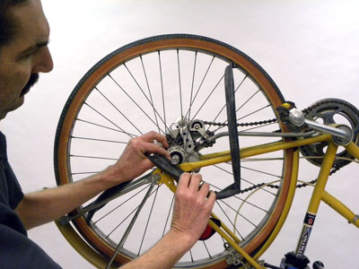 Figure 7. Work upside down and do not remove the wheel completely
Check the tire for a thorns, glass, etc. You can even pull the tire off to the left side and out of the bike. Inflate a new tube slightly, and install it over the left axle and up into the tire. Engage the valve in the rim hole and work the tube into the tire, and work the left bead back on to the tire.
After the rubber work is done, align the shifting interposer and pull the wheel back into the dropout. Center the wheel and secure axle nuts. Inflate tire. Reattach the shift cable and adjust the shifting. Lastly, go out and enjoy the shifting revolution.