Written by Calvin on May 5, 2011/Calvin's Corner
To Fixie, or Not to Fixie... Why Not Some of Each With the SRAM® Torpedo® Hub?
The article will review the service and installation of the SRAM® Torpedo® fix & free rear hub. Torpedo® branded hubs have a long history of coaster brake hub systems. SRAM® offers an interesting option in the Torpedo® fix & free hub. This hub allows freewheeling as any one-speed freewheel bike, but can then be adjusted without removing the wheel from the bike to a fixed gear option. The fixed-freewheel adjusting screw drives into the hub and displaces a carriage that frees a second set of internal locking pawls. This second set of pawls locks the rear cog from turning either direction.
Fixed gear riding has long been a rite of passage for some cyclists, while to others it is a way of life. The fixed gear means the rear sprocket is literally fixed to the rear hub. When the rear wheel is turning, so is the rear cog, so is the chain, and so are the pedals, either with or without you on-board the bike. I have personally ridden a fixed gear during a certain time and phase of my career, though presently I feel I am beyond that now. Fixed gear riding is an acquired skill and requires concentration and skill during the learning process. The legs must be kept relaxed even when not pedaling. If the rider forgets this for a moment, the momentum of the bike will lift the rider up and out of the saddle, not that this has happened to me... much.
NOTE: It has been a fashion, some might say a tradition, or a culture, for some cyclists to ride a fixed gear on the street without any hand brakes. This is not recommended. The physics of of the forces required to stop quickly cannot be duplicated by slowing the legs on the rear wheel alone and/or skidding. If this were possible, humans would be capable of acceleration from zero to 20 mph in but 3 seconds, and Newton’s First Law would not require that more braking force be applied.
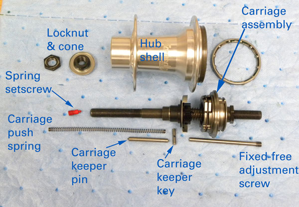 Figure 1. The parts of the SRAM Torpedo Fixie Freewheel hub
SERVICE—DISASSEMBLY
The Torpedo can be taken apart for cleaning and greasing (figure 1). The right side assembly, however, should be considered as a unit and not completely disassembled. It is recommended to work slowly with any new system, and to keep parts organized as you work. Take notes and/or images as you progress.
1. Remove wheel from bike.
2. Remove both axle nut and washers from both sides.
3. Remove cog snap ring, cog and dust cover from right side. Use a screwdriver and dislocate the ring at one of the three splines (figure 2).
4. Hold hub in an axle vise such as the Park Tool AV-1 or AV-4. Left side should be facing upward, with drive side down to vise.
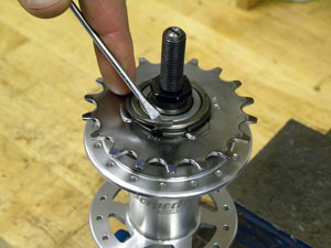
Figure 2. Remove snap ring, cog and dust cap
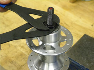
Figure 3. Remove locknut and cone from left side
5. Use a 13mm cone wrench to hold the left side cone and loosen the left side locknut with 17mm cone wrench (figure 3). Remove both locknut and cone.
6. Lift wheel or pull axle assembly from hub. The driver assembly has two sets of pawls (figure 4). One set is for freewheeling, the second set comes in only when locked for fixed riding.
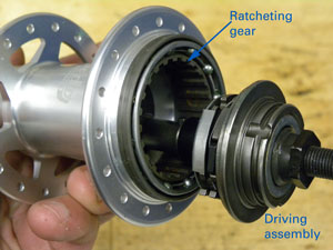
Figure 4. The driver and ratchet inside hub shell
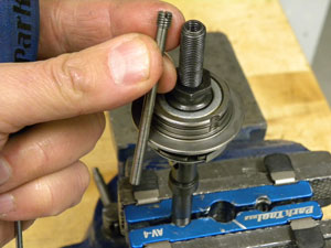
Figure 5. Adjusting screw to switch from freewheeling to fixed mode
7. Remove fixed-to-freewheel adjusting screw from right side (figure 5).
8. It is possible to pull the hub apart further. This will give access to the right side cone and axle bearings for greasing. HOWEVER, disassembly of the left side is difficult, and should be approached with caution.
9. Reverse axle in axle vise with left side facing upward. Place thumb and forefinger over axle end while loosening left side screw (figure 6). EXPECT the cap to shoot upwards with force form the coiled push spring inside. Control this by pressure from fingers. Coil spring can now be removed (figure 7).
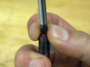
Figure 6. Control cap with pressure from fingers as left axle screw is removed
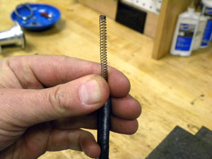
Figure 7. Remove coil spring
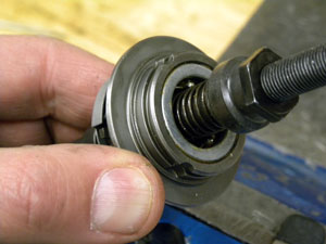 Figure 8. Right side axle bearings should be cleaned in place
10. Remove carriage push spring and carriage keep pin from inside axle.
11. Remove carriage keeper key (pin) from axle key way. Note orientation of key. Radius of key will face to radius of key way.
12. Right side axle bearings can now be accessed (figure 8). Do not remove right side cone. Flush and brush bearings, and dry with compressed air. Pack with grease for assembly.
SERVICE—ASSEMBLY
1. Install axle in axle vise with left side up.
2. Install carriage keeper key into axle key way. Radius of key will match radius in key way.
3. Install carriage keeper pin and push key side to side to check pin is in place.
4. Install coiled push spring into axle. Spring is difficult to reinstall without damage. Insert a spoke through spoke to allow compression (figure 9).
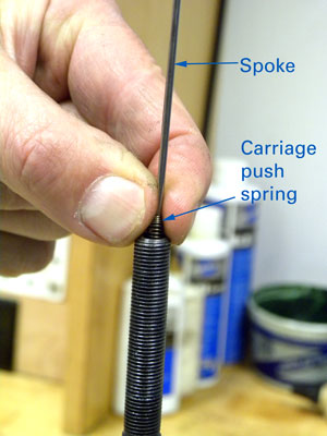
Figure 9. Use an inserted spoke through coil
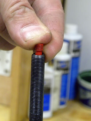
Figure 10. Install setscrew into left side of axle to hold spring
5. Push coil down into axle and hold secure with thumb and fore finger. Keep coil in axle and carefully work spring setscrew into place (figure 10). Snug setscrew into axle.
6. Reverse axle in vise. Install fixed-freewheel adjusting screw into right side.
7. Grease left side axle bearing and driver assembly bearings. Grease lightly all pawls.
8. Insert axle assembly into hub shell.
9. Install left side cone and locknut.
10. Adjust bearing play. Adjust in small increments so bearing adjustment is as loose as possible but without bearing play.
11. Install dust and rear cog. Install snap ring.
CHAIN TENSION & FIXIE-TO-FREEWHEEL ADJUSTMENT
Chain tension is important on one-speed bike. If there is too much chain tension, it will bind bearings and stress the chain. If the chain is set too loose, it may fall off the teeth and this may then in turn result in an accident for the users. Adjust the tension so the chain has approximately 1/2″ (12mm) up and down play between the front and rear cogs. Always test the tension to determine if there is any chance of the chain coming off the cogs. Tighten axle nuts to 30-40 Nm (266-350 inch pounds). Hold a wrench approximately 5 inches from the axle and apply a 60 pound effort.
The adjustment between a freewheeling system and the locked fixed gear system is made with the wheel in place. The adjustment cannot be done on the fly. The wheel must be stationary. The right side axle nut is made with a hole to accept a small flat bladed screwdriver. The axle is fitted with an adjusting screw inside the thread. By good design, the hole in the axle nut is smaller then the adjusting screw, making it impossible for the screw to come out completely and become lost. To lock the rear cog, turn the screw clockwise until it stops. To use the hub in freewheeling mode, turn the screw counter-clockwise 5 turns from this locked position.