Written by Calvin on September 30, 2008/Calvin's Corner
Shimano® Coasting System
This article will discuss the Shimano® “Coasting” system. The Coasting system uses a 3-speed internal hub. The shifting is done automatically the “Automatic Unit.” The electricity to operate the Automatic Unit comes from the dynamo (generating) front hub. From a speed of zero, the bike begins in the lowest gear (first gear). As the bike picks up speed, the dynamo hub produces more electricity and a winder mechanism in the Automatic Unit pulls a shift cable chaning to 2nd gear. With more speed comes more electrical power, and the winder pulls the shift cable more and the bike shifts to the highest gear, third gear. As the rider slows, the electrical current drops and the bike again shifts back to second and then to first gear.
The 2nd gear position provide a 1-to-1 gearing ratio. The hub turns the same speed as the rear cog. The 1st gear position allows the hub shell and spokes to turn slower then the hub, which reduces the stress on the pedals. 1st gear reduces the gearing approximately 25% from the 2nd gear position. 3rd gear position will turn the hub shell faster then the rear cog. This allows requires more force to turn, but will increase the gearing by approximately 30%.
The gearing options can be viewed in terms of a “theoretical three speed derailleur.” The 2nd gear or “neutral” option is basically the same as a one-speed. The gearing is simply the ratio of the front chainring to to the rear cog. For example, assume a bike uses a 33-tooth front ring and a 16-tooth rear. The rear wheel will turn about twice for each pedal revolution. If the front wheel has a circumference of 86-inches (common for the 700C tire sizing), the bike will move forward 129-inches per revolution. Switching to an easier gear, 1st gear, would be similar to shifting to a 21 tooth cog with the same front ring. Third gear, the fastest gear, would be a 12 tooth rear cog with the same 33 tooth front ring.
The front hub contains the dynamo and is secured to the frame by axle nuts. Use a 10mm hex wrench to loosen and remove the hub covers. Each side of the hub uses special non-turn axle washer against the fork dropouts. The hub cover aligns with these washers. If the covers is cracked or lost, the axle nuts are still functional.
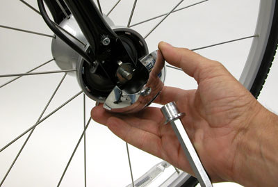
The hub dynamo cable is designed to go on the right side of the hub
The hub dynamo cable runs along the frame and from the Automatic Unit to the front fork. As with any wiring, is it best to have it secured to the frame. Supplement any build in holding devises with zip ties as necessary. When installing the covers, use care not to pinch or bind the dynamo power cable. It should not rub against the hub as it rotates. The connection terminal on the wire is not symmetrical. The ground connection on the terminal end must connect with the ground terminal of the dynamo. This is marked on both the wire and dynamo.
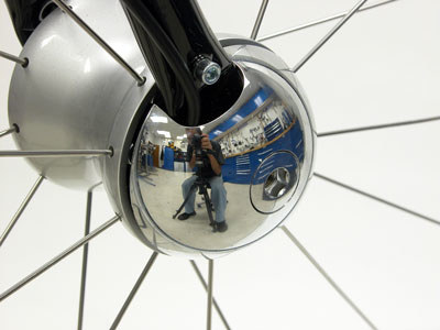
It is important that the right hub cover not pinch or cut the dynamo cable.
The Automatic Unit has an adjustment for personal preference on shifting priority. There are four possible settings plus an optional for only second gear at all times. Use a flat tipped screwdriver such as the SD-3 to turn the dial. The most counter-clockwise setting will delay shifting. This means the bike will stay in lower, easier pedaling gears longer as the bike picks up speed. Use this position if the rider prefers to spin at higher cadences. As the adjuster to turned clockwise, priority is given to larger gearing, or harder pedaling gears. The bike will shift to these higher gears more quickly. Use these clockwise setting if the rider has a relatively slower cadence style. The most clockwise position, the fifth position, is the “N” position. The bike will shift to the 2nd gear when used and stay there, making it effectively a one-speed.
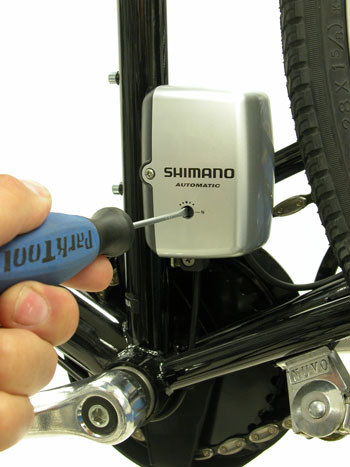
Adjusting the Automatic Unit of the Coasting system
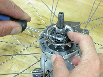
The rear hub shell contains a system of planetary and sun gears. It is basically a small transmission housed inside the hub shell. An adjusting rod on the right side is depressed to move the gearing inside the hub.
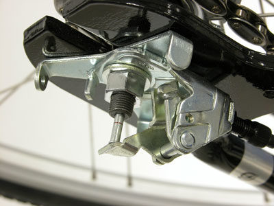
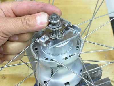
The Coasting system uses an internal coaster or back-pedaling brake. Like other coaster brakes, there is a brake arm that must be fixed to the frame. The Coasting system uses a plate system rather then the traditional coasting brake with extended arm and chain stay strap. The brake arm unit is also secured to the dropout with brake arm fixing bolts.
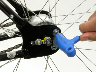
Loosen the brake arm fixing bolts before loosening the axle nut
The drive side uses a cover fixing stay for the domed shaped cover. The bell crank unit is then mounted under the axle nut and secured. The non-drive side on the hub uses a non-turn washer. Chain tension is set as with any two-sprocket bike. After chain tension is correctly set, install brake arm fixing bolts and washers on the non-drive side.
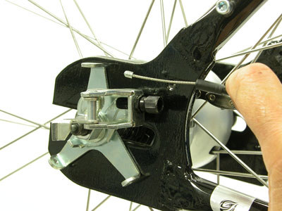
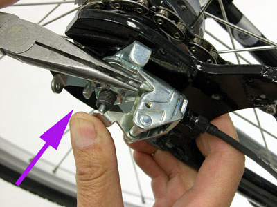
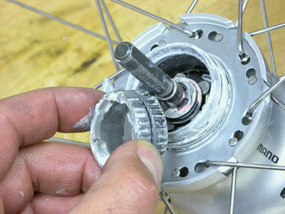
A metal cable system connects the Automatic Unit to the rear hub at the bell crank unit. The bell crank unit is a lever system that puhes on the adjusting rod in the axle.
The bell crank unit and adjusting rod of the Coasting rear hub in first gear
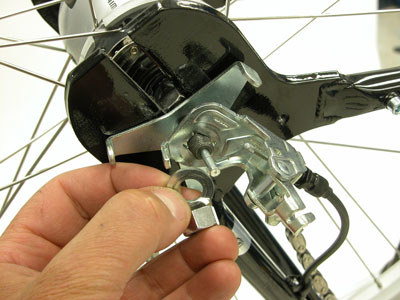
The shifting cable in double ended and is fitted through shift housing. One end has a small end to fit through the barrel adjuster.
Cable end and barrel adjuster of bell crank unit
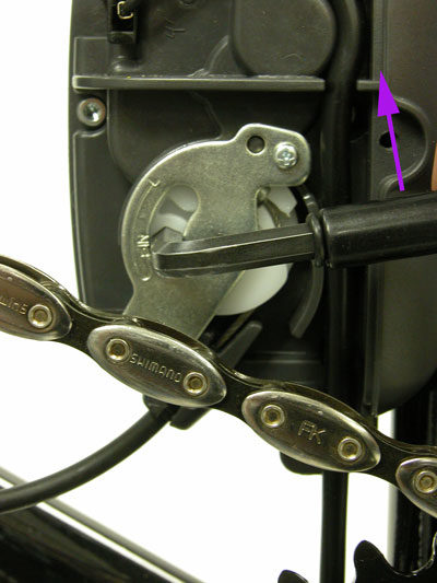
The other end has a end similar to a derailleur shift wire and fits into the winder mechanism of Automatic Unit. The cable must be attached before adjusting the hub gears.
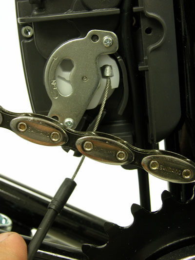
The winder mechanism of the Automatic Unit holds one end of the of the shift cable
As with other internal gear hubs, the system must be set when it is in “neutral” gear. There are two methods to achieve this. For either method, begin by rotating the Automatic Unit adjustment dial all the way clockwise to the “N” position. Rotate the front wheel and charge the Automatic Unit, causing it to pull the cable and bell crank unit to the 2nd gear position. Inspect at the juncture of the right side axle end and the push rod. There is a small machined circle on the axle. Use the barrel adjuster to change the effective housing length until the machined mark is flush with the axle end.
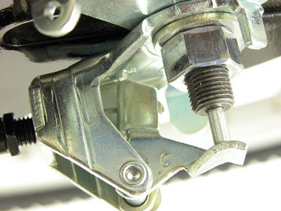
Cable tension adjusted so mark in rod is flush with axle end
OPTIONAL ADJUSTMENT PROCEDURE
The Coasting system can be calibrated without charging the Automatic Unit. Remove the cover and inspect the right side for the winder unit. In the winder unit will be a hex fitting for a 5mm wrench. Insert a 5mm wrench and rotate the unit clockwise unit the wrench hits the metal stop plate.
Rotate back clockwise slightly until a stop if felt. Inspect the hex fitting and the stop plate. The flat of the hex fitting should be aligned with the “N” mark on the stop plate.
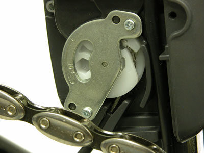
Align hex fitting in winder unit and the “N” mark in stop plate
REAR WHEEL REMOVAL
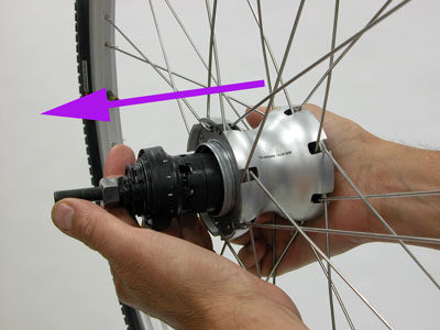
The rear wheel is removed from rear-facing dropouts. Remove both left and right side covers. Remove brake arm fixing bolts and washers. Loosen axle nut. Note orientation of the non-turn washer. This washer is used to prevent the axle from rotating in the dropout.
Disengage the cable from the bell crank unit. Depress the adjusting rod and pull cable end from lever. Pull lever away from axle and remove adjusting rod. Use a 15mm wrench to loosen and remove axle nut.
Remove bell crank unit and cover fixing stay bracket. Disengage chain from chainring and pull wheel back and out of dropouts.
When reinstalling wheel, the process is the reverse. Do not install adjusting rod or shift cable until chain tension is properly.
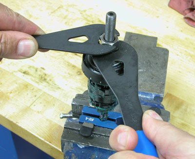
REAR HUB OVERHAUL
The rear hub can be overhauled if necessary. The hub is sealed well, and should not require frequent maintenance. The main purpose of an overhaul would be to clean and grease bearings. It is not necessary to dismantle the assembled unit to access the bearings.
a. Begin by removing rear wheel and clamping wheel in axle vise with right side upward.
b. Remove snap ring holding sprocket, and remove sprocket from hub.
c. Remove both left hand locknuts. Rotate brake arm unit as necessary to access nuts. Lift off brake unit.
d. Remove brake shoes from left side.
e. Push internal assembly unit from the left toward the right. Push on end of axle.
f. To access bearings, remove right side cone locknut and cone.
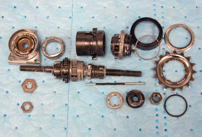
The internal parts of the Coasting hub.
FRONT HUB OVERHAUL
The front hub requies special 8-point socket tool to remove the dynamo from the hub shell. Service without these tools is not recommend. Contact Shimano for the tools.
AUTOMATIC UNIT
The Automatic Unit is attached to the frame with a special bracket. The Unit will slide over the bracket and secure with a screw.
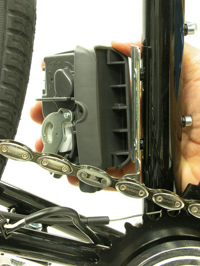
Bracket of the Automatic Unit
The Automatic Unit cover is held on by two screws. This permits adjustment or installation of the shift cable. It is recommended that the Automatic Unit not be opened. There are no effectively serviceable parts. The dynamo hub cable charges a capacitor inside the Automatic Unit. The capacitor is continuously charged when the bike is moving. The charge is used to both turn the winder and to hold the hub crank bell unit in place. The Automatic unit is also fitted with a potentiometer or variable resistor. This is a control similar to the volume control on a radio. It is used to control the shifting priority of the Automatic Unit.
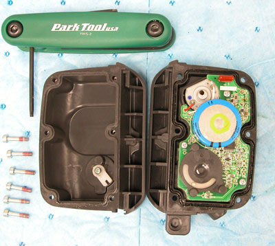
Inside the Automatic Unit