Travel Agent™ Installation and Adjustment
This article will review the installation and adjustment of the Travel Agent™ brake cable system.
Getting Started
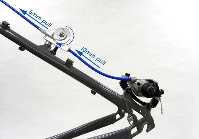
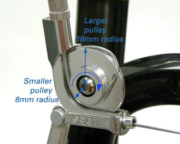
The Travel Agent™ is a brake cable pulley system that increases the amount of cable pull (Figure 1). The cable is routed around an inner pulley, and then is routed to a larger outer pulley. As the inner pulley rotates, the outer puller will travel around a greater circumference and this increases the linear distance of cable pull. While this system increases the amount (distance) of cable pull, it does not increase the total amount of work done on the cable to stop the bike.
The hand brake levers are of course operated by pulling the lever with the fingers. This moves the brake cable end, and the cable then moves some distance and with some amount of force according to the design of the lever. A lever designed to pull relatively large amounts of cable does so by sacrificing pulling force. This is because there is a trade-off between cable pulling force and cable travel.
Consider older brake levers used for cantilever brakes. The distance between the lever pivot and the brake cable end determines the amount of cable that is pulled. From the older style flat-bar lever pivots to the brake end fitting are typically 21mm (figure 2). This in effect creates a circle with a circumference of about 132mm. If the lever is pulled so it moves from fully open to about 20-degrees, it will pull about 7mm of cable through the housing, and this in turn pulls the arms and brake pads to the rim.
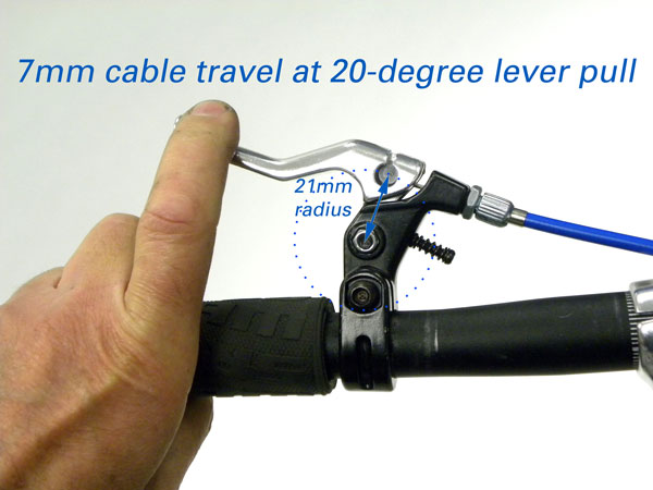
Figure 2. Flat bar lever designed for cantilever brakes
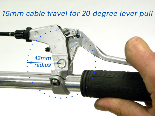
Figure 3. Long travel brake lever
The modern linear pull levers have a pivot to brake-end radius of about 42mm, and a large circumference compared to the cantilever compatible lever (figure 3). The linear pull levers when pulled 20-degrees will draw about 15mm of cable through the housing. The long arms on the linear pull brakes at the rim are designed to work with this great amount of cable pull from the linear pull lever.
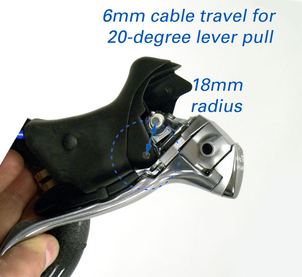
Modern drop-bar shift/brake levers have a relatively smaller radius compared to flat bar levers (figure 4). Pulling the lever about 20-degrees will pull only 6mm of cable through the housing. The dual-pivot brakes used for these levers are designed to work with this relatively small amount of cable travel.
The Travel Agent™ is useful when an incompatible hand brake lever is matched with a brake caliper requiring longer cable pull. For example, the common road lever should never be used with the linear pull caliper brakes, or a mechanical disc brakes. The long arms of linear pull caliper and the mechanical disc MTB brake both require a relatively large amount of cable pull. Using a road lever designed for dual pivot rim calipers will mean the cable will be pulled enough to work effectively. The Travel Agent™ mechanism was designed as a solution for just this problem. The Travel Agent™ increases the amount of cable travel and allows the caliper brake to properly apply pressure to the rim or disc.
The Travel Agent™ come in two versions. There is the “noodle replacement” version and an “in-line” version. The noodle-replacement is mounted directly to the caliper arm. This design has two cable hole options in the top of the Travel Agent™ body. Routing the cable so it travels directly around only the larger outer pulley will not increase the amount of cable pull (figure 5). This Travel Agent is simply a different type of “noodle” with this option (figure 6).
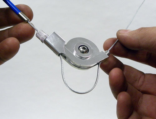
Figure 5. Routing cable for a direct pulley with no increase in travel
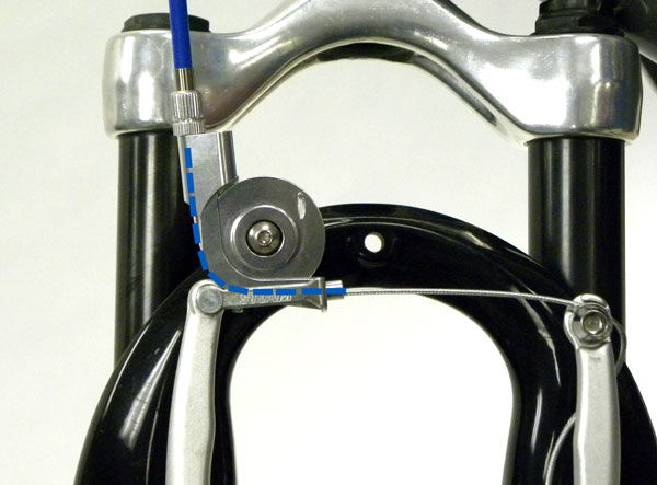
Figure 6. Travel Agent™ used as a noodle-replacement without any multiplying effect
Cable puller using the noodle-replacement will double when the cable is routed to the inner pulley and then fed to the outer puller (figure 7). The inner pulley will rotate the same angular amount as the outer pulley, but the outer pulley will pull more cable.
Installation
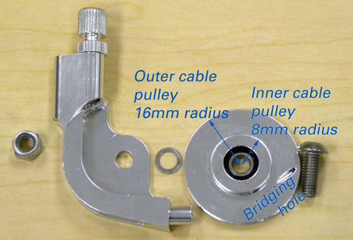
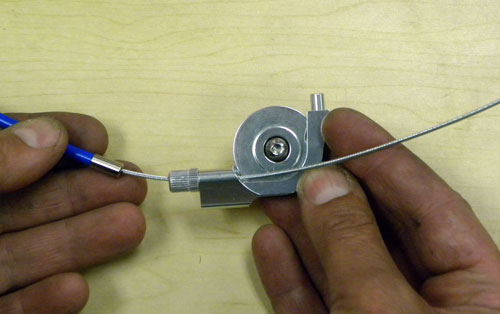
When installing Travel Agent™ units, install new cables at the same time. The old cables will be too short and new cables are always a good idea. Route the cable and housing through the adjusting barrel and cable through the hole that is directed at the smaller or inner pulley (Figure 8).
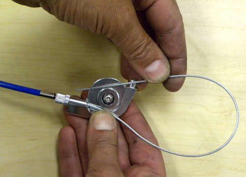
Pull out cable slack by hand and route the cable around the smaller pulley and back and through the access hole (“bridging hole”) in the pulley (figure 9). The access hole should be aligned so hole is counter clockwise, or relatively near the barrel adjuster.
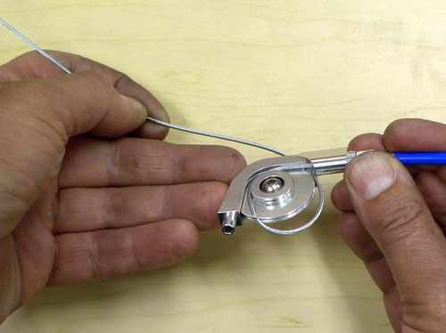
Feed the cable out the back side of the Travel Agent™ body and back into the body along the outer pulley grove (figure 10).
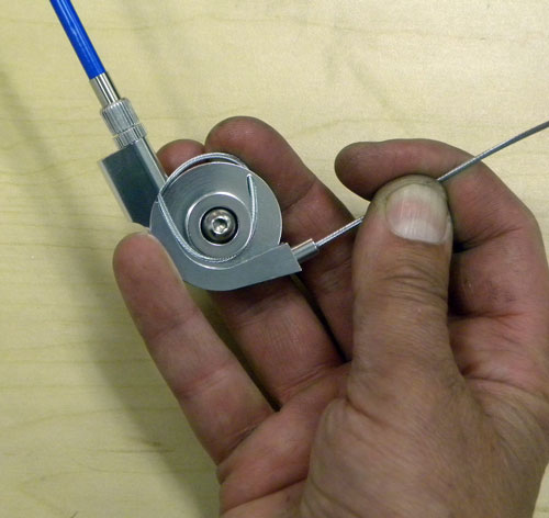
The cable continues around the Travel Agent™ and out the hole (figure 11). It is now ready to fit into the caliper linear pull brake carrier in place of the “noodle”.
It is critical the cable at the bridging hole be adjusted so that cable transition never contacts the brake linkage during operation of the brake. If the cable routed at the bridging hole strikes the brake-noodle carrier or the Travel Agent body, it will jam and not allow further pulling or braking. Imagine a line through the pulley center that is parallel to the barrel adjuster and cable entrance. This line defines a 12:00 and 6:00 axis of a clock face (figure 12). The bridging hole should not be allowed to rotate past the 5:00 position when the cable is pulled by the hand lever (figure 13).
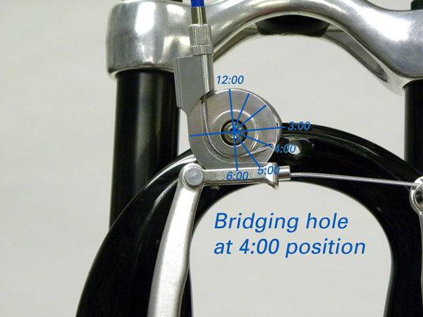
Figure 12. Cable bridging hole sitting at the 4:00 position
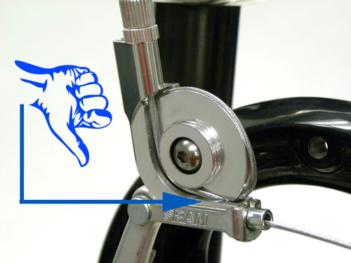
Figure 13. Cable transition at the 5:00 position will result in braking failure
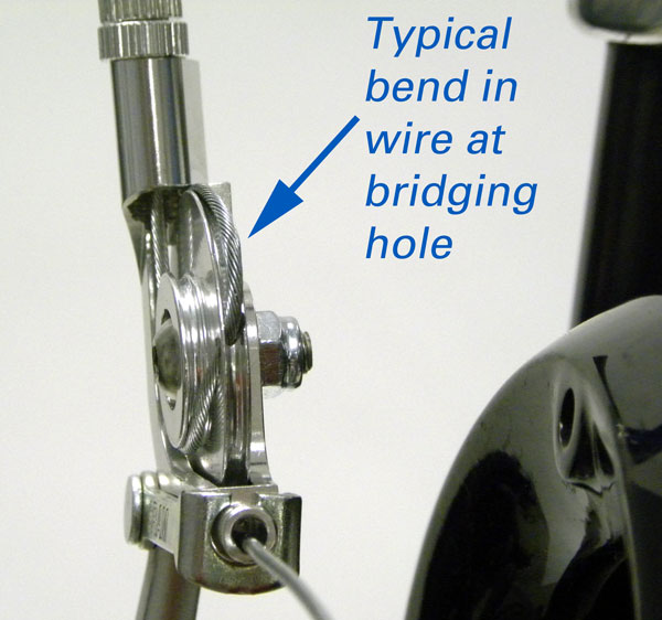
The brake cable must make a sharp transition through the bridging hole from the inner pulley to the outer pulley. This will kink and flatten the cable wires to a small extent, and this is normal for this system. Inspect this transition anytime the bike is serviced and replace cable as necessary.
The Travel Agent™ are also available in an “in-line” configuration. It is placed in the middle of the housing route, for example along the seat stay. This is useful for mechanical disc brake calipers or linear pull brakes when used with common drop bar road levers (figure 15).