RockShox® Rear Shock Service—Monarch 4.2
This article will review the service of the RockShox® Monarch rear shock.
Getting Started
Rear shocks are found on most full suspension bikes. Full suspension bicycle frames use a linkage system to allow the rear axle to move up and down independently to accommodate uneven terrain. The rear shock pushes back against the linkage and compresses when a large enough load (hit) is applied.
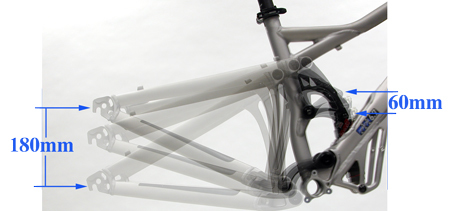
As the rear axle moves, the linkage attached to the shock moves, but to a lesser degree. In Figure 1, the rear axle moves approximately at a 3 to 1 ratio. If the axle moves upward 6mm, the shock compresses about 2mm. As an example, the Monarch shock has a total travel is 63mm. Generally, a shock should be compressed approximately 10–25% of the shock travel as “sag.” Sag is the slight compression of a shock from the weight of the rider as they simply sit on the bike. During a very large hit or impact, if the rear axle on the example bike were to travel 180mm upwards, the shock will compress approximately 60mm, nearly the full amount of potential compression.
Rear shocks are available in various designs. Bike designs will specify a certain rear shock length as measured from eyelet to eyelet. Rear shocks will also vary in the amount of available travel. Shocks use a two number system to designate both features. These number may be specified in either metric or inch increments. The first number is the full length between eyelets of the extended shock. The second number is the amount of possible compression. Numbers are rounded for convenience. Below is listing of available specifications of various brands and models:
Metric Specs are listed first, then as (inches):
- 140 x 25 (5.5″ x 1″)
- 152 x 32 (6″ x 1.25″)
- 165 x 38 (6.5″ x 1.5″)
- 190 x 51 (7.5″ x 2″)
- 200 x 51 (7.875″ x 2″)
- 200 x 57 (7.875″ x 2.25″)
- 216 x 63 (8.5″ x 2.5″)
- 222 x 70 (8.75″ x2.75″)
As an example, the RockShox® Monarch 4.2 HV 216x63 rear shock is 216mm from eyelet to eyelet before installation or compression. There is 63mm available from full extension to full compression.
Rear shock removal procedures will vary according to the frame manufacturer. Mount the bike in a repair stand to relieve any pressure on the shock from the weight of the bike. Loosen and remove both upper and lower eyelet bolts (Figure 2 and 3). Takes note of the shock orientation to speed reinstallation.
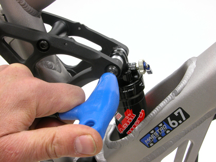
Figure 2. Remove bolts from upper and lower shock eyelets
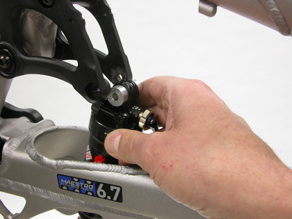
Figure 3. Pull shock free from linkage
To service the rear shock, it is necessary to remove all the mounting hardware from the shock eyelets. Some mounting hardware will be removable by hand or with pliers. Try not to unnecessarily scar the hardware, and note orientation of anything removed. Use notes, zip ties, or digital images to assist you in recalling correct assembly orienation.
Some designs use mounting hardware that is a press fit in the shock eyelet. There are tools available from the shock manufacturers for pressing out this mounting hardware. It is also possible to find sockets that match the bushing size, and to tap out the bushing.
Shock Disassembly
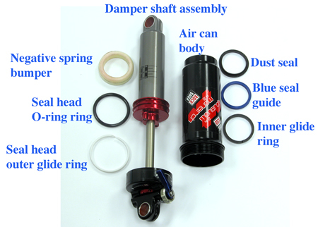
The internal parts of the RockShox® Monarch 4.2 is seen in Figure 4.
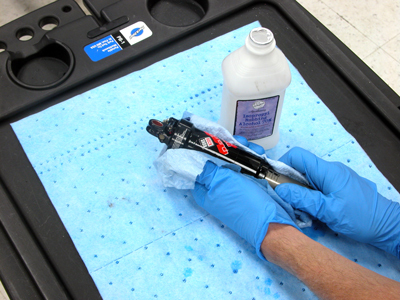
It is important not dirt get inside rear shock. Clean entire outer surface with isopropyl alcohol and a soft cloth before performing any further work (Figure 5).
Release all pressure from the shock. At the air-can body, remove cap from air valve and use a small hex key to depress Schrader valve (Figure 6). There is also pressure inside the damper body. If the damper body is not being serviced internally, it is not necessary to release this pressure.
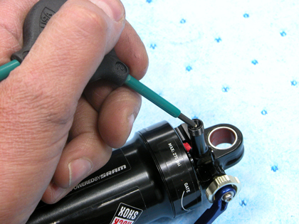
Figure 6. IMPORTANT: Release air pressure from shock
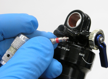
Figure 7. Remove valve core to clean and lubricate
The Schrader valve core may also be removed for cleaning and lubrication of valve seals (Figure 7). Reinstall the valve core after wiping clean and lubricating with a small amount of suspension fluid.
Secure the air can eyelet in the soft jaws of a vise, (the AV-5 works well) and clamping between the holes in the jaws. The larger side of the rear shock should face downward. Grab the air-can body firmly by hand and turn the body counter-clockwise (Figure 8). Some air pressure may escape at this time. Alternatively, a “strap wrench” will add leverage and not hurt the air-can (Figure 9).
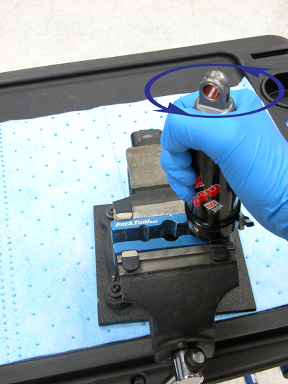
Figure 8. Rotate air-can counter-clockwise to unthread
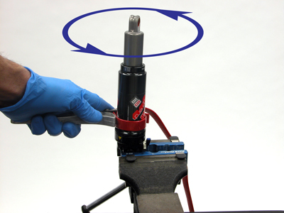
Figure 9. Use a strap wrench if available
Pull upward on air-can to remove the air-can body from shock damper (Figure 10). NOTE: The damper shaft assembly body should not be disassembled. Service of the damper should be performed only by a trained professional mechanic.
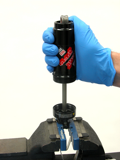
Figure 10. Pull air-can up and off of damper shaft assembly
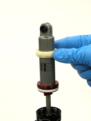
Figure 11. Slide the negative spring bumper up and off damper
Remove the negative spring bumper from damper body (Figure 11).
Remove the glide washer from the damper. Use split in washer to open and slide washer off of piston. Remove O-ring. Push from O-ring from one side, and then push ring up and off piston (Figure 12).
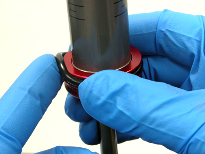
Figure 12. Remove O-ring from piston
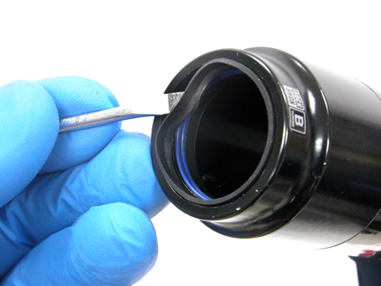
Figure 13. Remove dust seal
The air-can contains a series of seals and bushings. Hold the air-can with the small opening upward. Use a seal pick or small tipped screwdriver to remove the black rubber dust seal (Figure 13).
Located below the black dust seal is a blue glide seal. The blue glide seal is a tighter fit inside the air-can then the dust seal. It is best to use a seal pick or a pointed spoke to remove blue seal (Figure 14). NOTE: Work with care and do not gouge or damage the air-can surface.
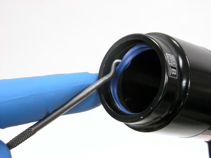
Figure 14. Remove the blue glide seal
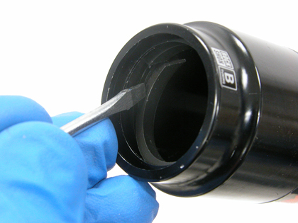
Figure 15. Remove internal glide ring from air-can
The air-can contains an internal air-can ring below blue glide seal. It will be necessary to very carefully use a seal pick to remove the inner bushing. Find the split in the ring. Work bushing split inward and free bushing from air-can (Figure 15).
NOTE: Do not scratch the inside of the air-can, especially where piston travels. Any scratches will result in air leakage, making the rear shock dysfunctional.
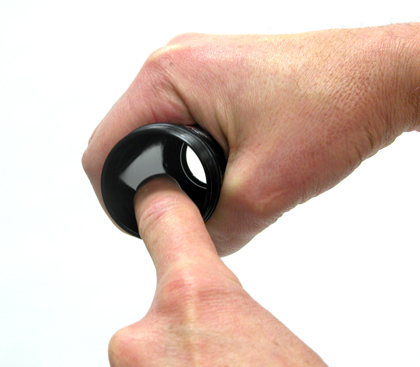
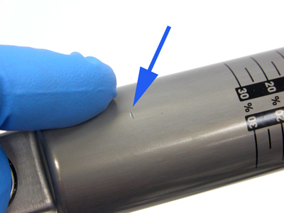
Clean inside air-can with isopropyl alcohol (rubbing alcohol) using a clean rag. Inspect inner surface of the air-can for any blemishes, scratches, or rough surfaces (Figure 16). Damage to surface may prevent proper piston seal under pressure. Damaged shocks should be replaced.
Also inspect outer surface of shock damper for scratches or damage (Figure 17).
Shock Assembly
Begin assembly by installing new O-ring and glide ring on piston of damper body.
Install internal glide ring inside air-can. Narrow lip in ring faces toward large part of air-can. Overlap the split in the ring to allow it to enter the can (Figure 18). Place ring in machined recess at narrow end of air-can.
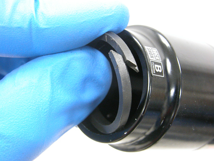
Figure 18. Install glide ring
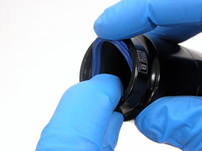
Figure 19. Install blue glide seal over internal glide ring
There will be a gap above internal glide ring. Install the blue glide seal above internal glide ring in this recess (Figure 19). Push one section of the seal in place, and then work the seal fully into the air-can.
The black dust seal installs last. The thin lip of the seal faces away from can. Push one section of the seal in place, and then work the rest of the seal into air-can (Figure 20).
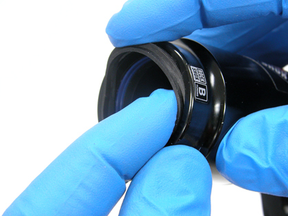
Figure 20. Install the black dust seal
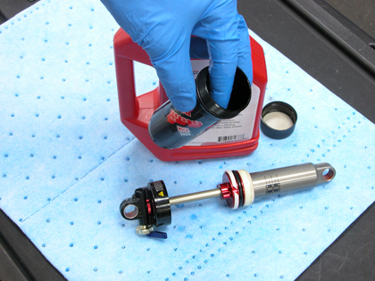
Figure 21. Lubricate inside the air-can and all seal with suspension fluid
Lubricate the inner surface of the air-can with a small amount RockShox® suspension fluid. Also lubricate the seals in the air-can, as well as damper piston O-ring and glide rings (Figure 21).
Guide air-can over the shock damper assembly. Push the air-can onto the damper to engage the threads of the damper shaft assembly (Figure 22).
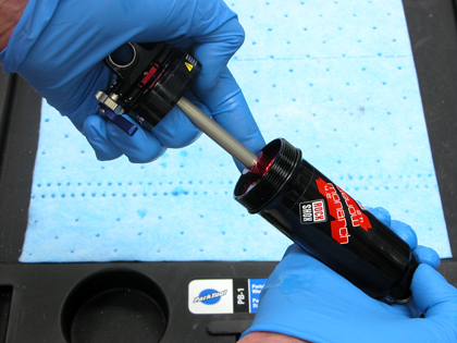
Figure 22. Install air-can onto damper shaft assembly
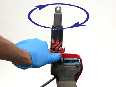
Figure 23. Tighten air-can fully using a strap wrench
Place the damper shaft assembly eyelet in the soft jaws of the vise. Thread the air-can onto damper body and tighten firmly using a strap wrench (Figure 23). If no strap wrench is available, tighen by hand with force. Do not use pliers or other tools to tighten the air-can. If air-can is wet with fluid, clean off the fluid to allow better grip.
Inflate the rear shock. Pressure recommendations are available from shock manufacturer.
Reinstall any hardware that was removed to service the shock. Use manufacturer’s hardware installation tools when available. Alternatively, it is possible to support the eyelet with tubing larger than eyelet. Hardware can then be carefully tapped into place.
Reinstall the rear shock. Fully secure the mounting bolts to the specifications of the bike manufacturer.
Related articles
RockShox® Pike® Suspension Fork Service View Article