Mechanical Disc Brake Alignment
A rubbing or underperforming disc brake can often make a ride frustrating. Regardless of brand and model, this article will help you gain the knowledge you need to adjust mechanical disc brakes.
Preliminary Info
- Appropriate wrench for pad adjuster, pinch bolt and mounting bolts. This may include T25 Torx®-compatible, or 3, 4, or 5mm hex: Hex & Torx®-Compatible Tools
- Torque wrench or torque driver with appropriate bits: Torque Tools and Bits
- Cable cutter: CN-10
- Flashlight & light piece of paper
Mechanical brake systems use a cable to actuate a lever arm on the caliper that engages the pads. Hydraulic systems use fluid through a hose to engage the pads. Here are the key components of the mechanical disc braking system:
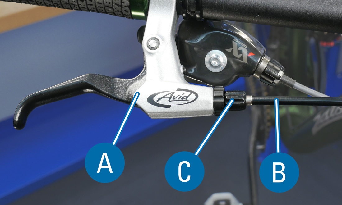
- BRAKE LEVER: The brake is actuated by a brake lever at the handlebars.
- CABLE & HOUSING: On a mechanical system, the brake lever pulls a cable, which runs through housing down to the brake caliper.
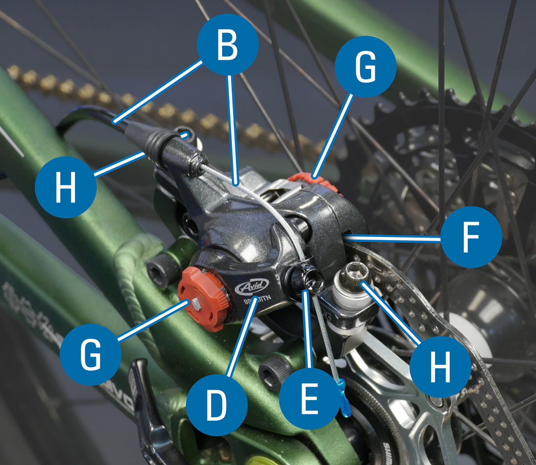
- BARREL ADJUSTER: The housing can effectively be lengthened or shortened with the twist of a barrel adjuster, which may be found at the lever and/or the caliper.
- LEVER ARM: The brake cable actuates a lever arm. Most mechanical caliper designs have 1 lever arm that moves only the outer brake pad when actuated. The rotor then flexes over into contact with the inner most pad. There are also designs that have 2 lever arms. On these calipers both pads move evenly into the rotor.
- PINCH BOLT: The cable is secured to the lever arm using the pinch bolt.
- PADS: The lever arm squeezes the brake pads to the rotor, causing friction to slow or stop the bike. Brake pads consist of braking compound bonded to a backing plate.
- ADJUSTERS: Calipers are equipped with pad adjusters that move the brake pads in or out from the rotor. Some calipers have only one adjuster that moves the inner pad, while other calipers have both an inner and outer pad adjuster.
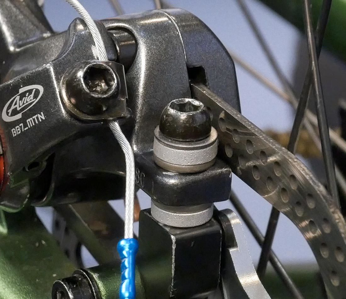
- MOUNTING BOLTS: Caliper disc brakes secure to the frame or fork using two mounting bolts. The location of these bolts can vary depending on the frame mount standard: Post Mount, IS Mount, or Flat Mount.
- MOUNTING HOLES: Disc brake systems are equipped with wide holes that allow for lateral movement relative to the rotor. These can be found on the caliper body (post mount), the frame (rear flat mount), or the caliper adapter (front flat mount).
Alignment Procedure
Before beginning the caliper alignment process, it is important to check other components that could effect your brake adjustment are set correctly.
- Ensure that the wheel is fully seated in the drop outs. This, in turn, ensures that the rotor is properly positioned in the caliper.
- Elevate the bike, spin the wheel and inspect the rotor in the caliper. If the rotor shows a lot of lateral movement, it can be difficult or impossible to adjust the pads to not rub. The rotor will need to be trued or replaced.
- Turn the barrel adjusters all the way in (clockwise) at the lever and at the caliper if applicable.
- Check that the lever arm is released and in its relaxed position by loosening the cable pinch bolt. This ensures full lever arm travel during braking.
- Pull the cable tight so it is free of slack and tighten the cable pinch bolt.
- Be careful not to move the lever arm when tightening the pinch bolt. This is important because the lever arm only has a small amount of useful motion.
Design-Specific Instructions
The alignment process varies depending on the caliper design.
Single Lever Arm — Inner & Outer Pad Adjusters
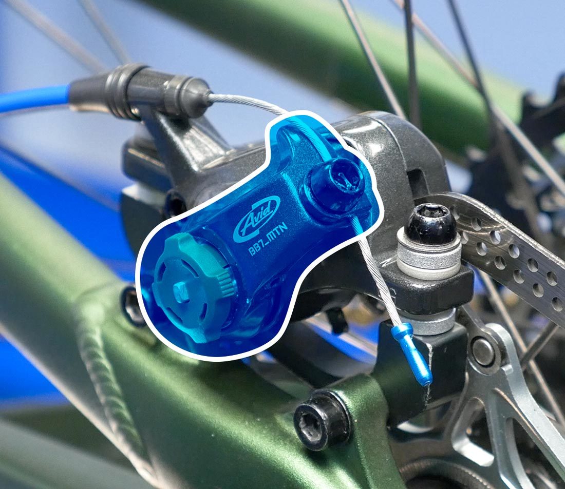
The cable pulls a single arm, which moves the outer pad
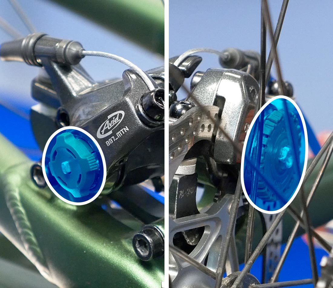
The outer and inner pads feature an adjuster
- Begin by loosening the caliper mounting bolts. This alows the caliper to float.
- Turn the outer pad adjuster all the way out (counterclockwise), then back in 1 full revolution. This leaves room for future adjustment.
- Turn the inner pad adjuster clockwise until the pads lock against the rotor.
- Snug the caliper mounting bolts to align the caliper body over the rotor. Full tightening will occur after good pad alignment is confirmed.
- Loosen both the inner and outer pad adjusters evenly, 1/4 to 1/2 turn
Single Lever Arm — Inner Pad Adjuster Only
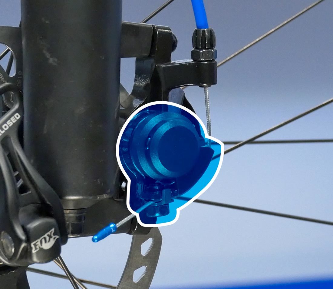
The cable pulls a single arm, which moves the outer pad
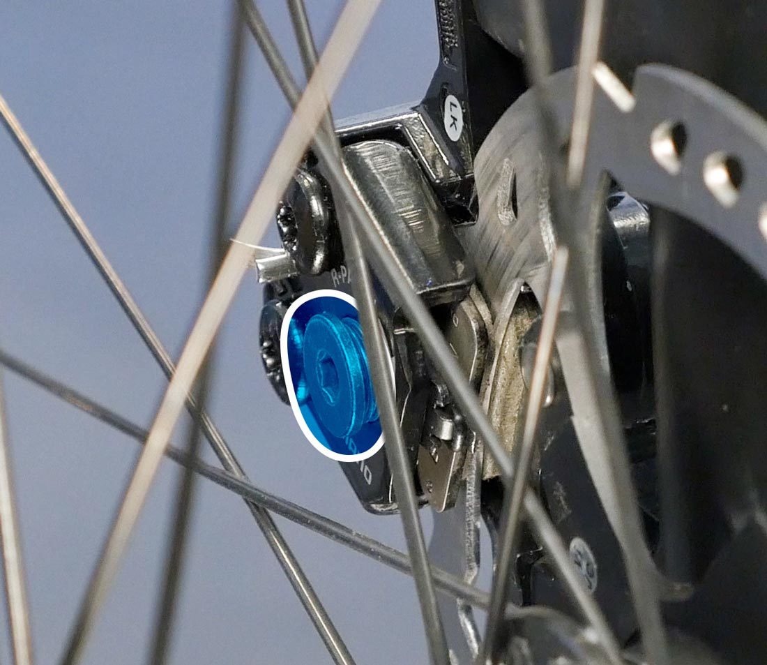
Only the inner pad features an adjuster
- Begin by loosening the caliper mounting bolts. This alows the caliper to float.
- Turn the inner pad adjuster all the way in (clockwise), then back off about 1/4 turn
- Pull and hold the brake lever tight. This aligns the caliper body to the rotor.
- Snug the caliper mounting bolts.
- Release the brake lever.
- Back off the pad adjuster another 1/4 turn.
Dual Lever Arm
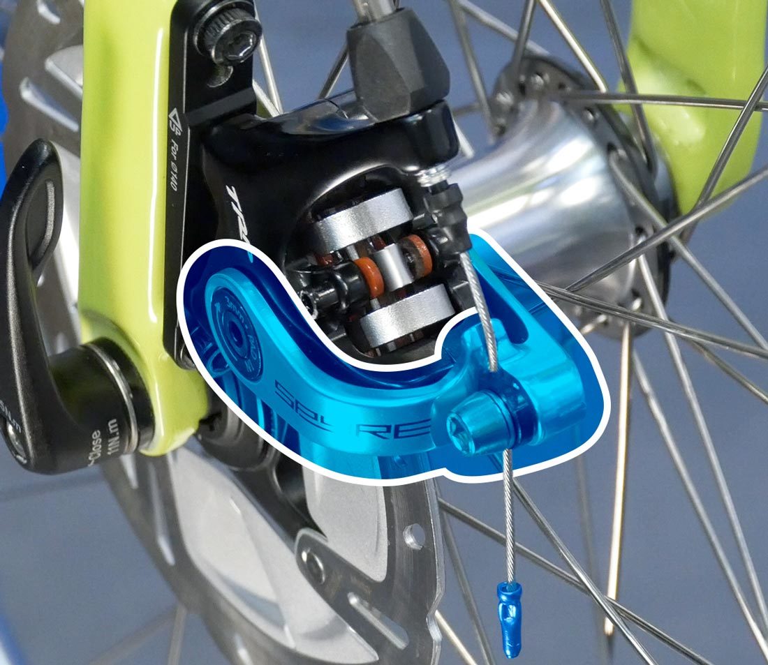
- Begin by loosening the caliper mounting bolts. This allows the caliper to float.
- Turn the inner and outer pad adjusters all the way out (counterclockwise).
- Pull and hold the brake lever.
- If the lever goes all the way to the handlebar without the brakes making contact, release the lever and tighten both pad adjustment screws 1/2 turn. Repeat tightening evenly until pad contact is felt at the lever.
- Snug the caliper mounting bolts to hold the alignment of the caliper body over the rotor. Full tightening will occur after good pad alignment is confirmed.
- Release the lever.
Final Adjustments
These final adjustments apply to all mechanical disc brakes. The end goal is a caliper that is parallel to the rotor, with even gaps on each side and an adequate lever feel. Even though setting the pads against the rotor should theoretically have aligned the caliper correctly, it is common for further adjustments to be required.
Lever Position
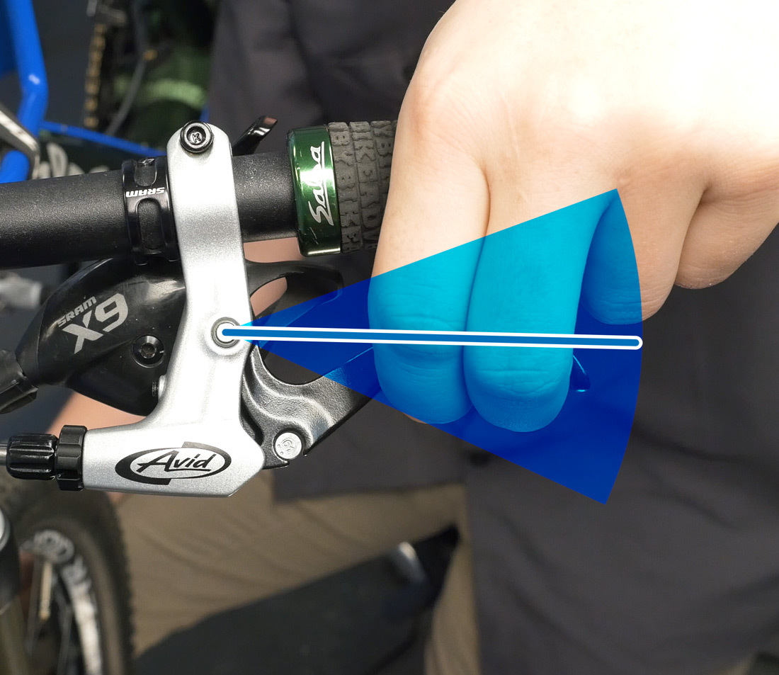
- Pull and release the brake lever a few times to check the clearance at the grip. Check that the lever travel feels adequate to slow and stop the bike. Typically, the pads should feel like they are contacting the rotor at a minimum of one-half the lever travel.
- Make adjustments as necessary using the pad adjusters, moving the pads in and out evenly on both sides.
Pad Rub
- Spin the wheel and check for pad rub.
- If there is no pad rub, the alignment is complete — skip to FINAL STEPS.
- If the wheel slows quickly, or makes a rubbing noise, the pads need further adjustment.
- Inspect the alignment of the pads to the rotor. You may need to reorient the bike for a better view.
- It is helpful to backlight the caliper body by shining a light on a piece of white paper or material. This makes the pad clearances easier to see.
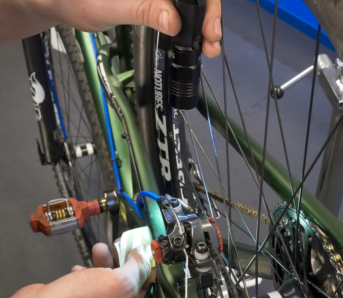
A small flashlight pointed at a sticky note held behind the caliper...
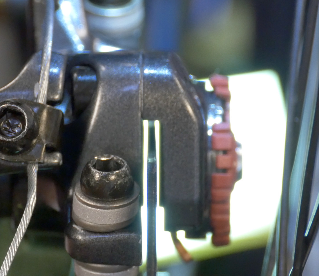
...makes the alignment of the pads to the rotor much more visible
- If the pads are not parallel to the rotor, the caliper body needs to be adjusted. Loosen one bolt, move the body slightly to the side that has no gap, snug the bolt and re-check the alignment.
- Keep in mind that making one adjustment may affect others.
- If pads appear parallel, but there is still rubbing, loosen the pad adjuster on the side with pad rub in 1/4-turn increments until it is gone.
- Re-check the clearance at the lever and adjust as necessary.
For calipers with inner pad adjustments only, the procedure for adjusting outer pad clearance is different:
- Loosen one of the mounting bolts, move the caliper a small amount toward the side that is rubbing, and re-snug the bolt.
- Repeat these steps until the rubbing is eliminated.
Final Steps
- Finish by fully tightening the pinch bolt and each mounting bolt. Typical torque specs are about 6 Nm for the mounting bolts and 4 Nm for the pinch bolt.
- If you have installed a new brake cable, or if the cable has excessive slack, cut the cable roughly 1 inch past the pinch bolt and add an end cap to prevent fraying.
Other Considerations
The brake is now properly adjusted and ready to test ride. Here are some other considerations that may come into play during this process:
Brake Pad Wear
As the pads wear, you will need to make further adjustments to keep the lever feel consistent. Tighten the pad adjusters to bring the pads closer to the rotor. Move the adjusters evenly in small increments and test at the lever.
Calipers with a single pad adjuster will need to reset the caliper position from scratch as the pads wear. Refer back to section #2.
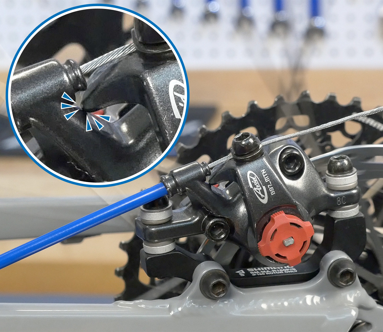
IMPORTANT: Do not use the barrel adjuster to move the pads inward as they wear. This will eventually move the lever arm to a position where it is contacting another part of the caliper, preventing the pads from contacting the rotor.The barrel adjusters should only be used to take out cable slack as the cable and housing system settle in.
Cable & Housing Wear
Worn, dirty or corroded cable and housing can drastically affect the performance of the braking system. Replace these components if necessary — see Brake Housing & Cable Installation for Upright Bars or Drop Bars.
Mount Facing
In some cases, frame mounts may not be perfectly square to the rotor, causing lateral misalignment at the caliper. There is often no adjustment possible for this type of misalignment, but a professional shop may be able to face or machine the mounts with the Park Tool DT-5.2 to improve alignment.
Conical Washers
Some manufacturers use a system of mating conical washers. These help to align the vertical face of the pads to the rotors. These washers must be designed into the system, and cannot be added to brakes not designed for them. Additionally, if the brakes came with these washers they must be used. If there are conical washers only on top of the caliper, they should remain on top.
