In-Line Brake Levers
This article will discuss the installation of the in-line brake levers, also referred to as "cross levers."
Getting Started
- Hex wrenches
- CN-10
- Housing and ferrules
- Tape to secure brake housing
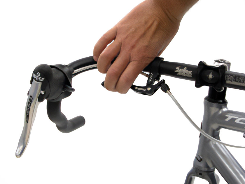
In-line brake levers are an additional set of brake levers that may be installed on drop-type handlebars. In-line levers are installed above the primary brake lever, and allow the rider to actuate the calipers while riding on the top part of the handlebar (Figure 1). The in-line lever pushes on the housing, effectively making it longer, which causes the brake caliper to close on the rim.
In-line brake levers are designed to clamp on specific bar diameters. Lever must be mounted to a compatible section of bar. Check the manufactures literature of the clamp to confirm compatibility. For most drop-style bars, the smaller outer section of the bar (where the primary lever is clamped) is approximately 23.4 mm. However, the larger bulged or center section may be 25.4, 26.0, 26.4, or 31.8 mm.
It is sometimes possible to reuse old housing and brake inner wire. However, it is recommended to install new brake housing and cables when installing in-line levers.
Brake Lever Installation
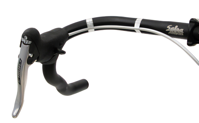
Remove the handlebar tape at least down to the brake lever. Remove the brake housing and cable (Figure 2).
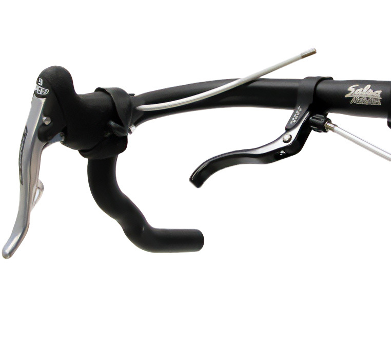
Mount the in-line lever to the top section of the bar (Figure 3). Do not route the housing under the clamp of the lever. Position the lever for comfortable reach and angle (Figure 4).
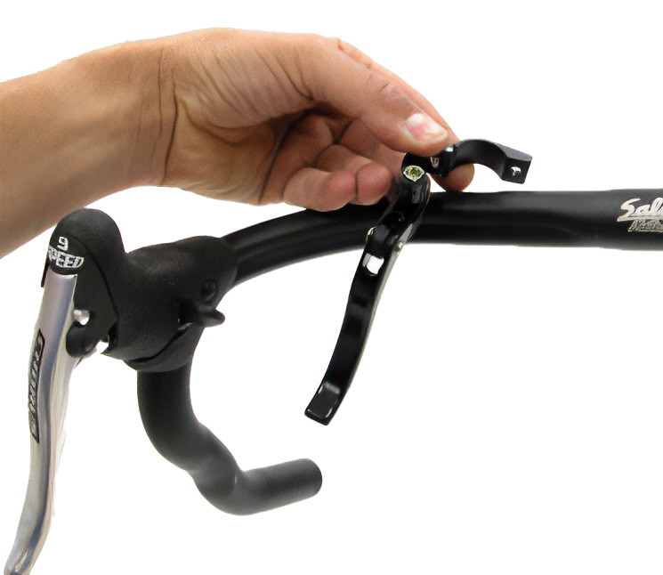
Figure 3. In-line brake levers
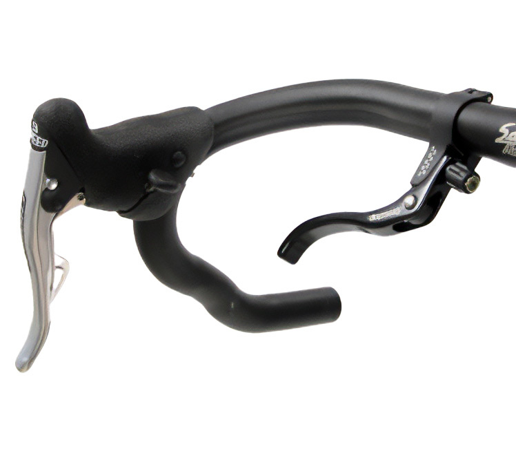
Figure 4. Adjust angle for comfort
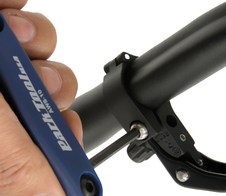
Tighten the lever to the bar (Figure 5). Do not route any housing under the clamp of the lever.
Housing & Cable Installation
Cut housing lengths for the in-line lever. There will be two sections of housing. One section goes from the primary lever to the in-line lever. The second piece of housing goes from the in-line lever to the brake caliper or frame housing stop as applicable (Figure 6). Use housing end caps wherever they will fit into levers or stops.
Feed the brake wire through the brake lever, through the first section of housing, through the brake lever, and through the second section of housing. Attach the brake wire to the caliper and adjust the brake as normal. Secure the first section of housing to the bar with tape (Figure 7).
Wrap handlebars. However, do not attempt to bring the bar tape to the lever as this may stress the housing (Figure 8).
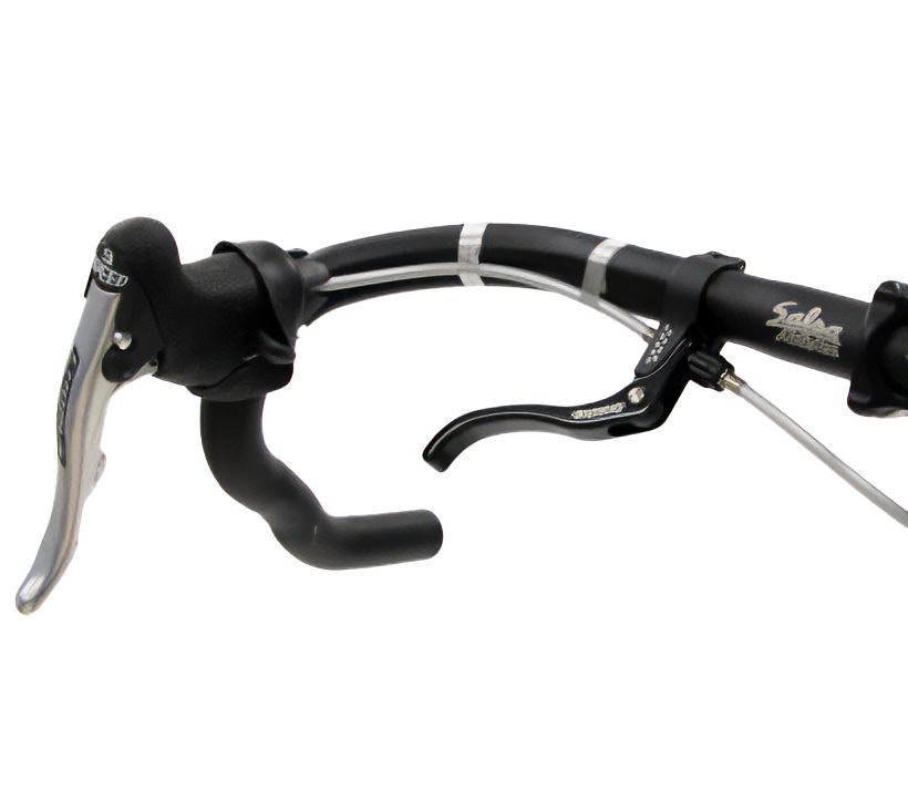
Figure 7. Housing is installed and ready to be wrapped
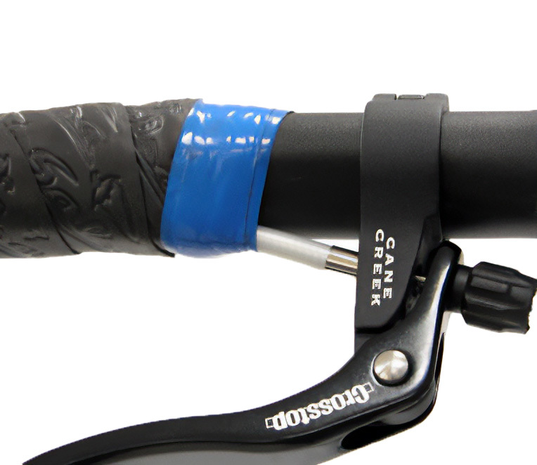
Figure 8. Allow the housing to reach the stop in brake lever
Related articles
Handlebar Tape Installation (Drop Bars) View Article