Determining Spoke Length for Wheel Building
A properly-built wheel begins with properly-sized components. In this article, we will outline how to determine proper spoke length for your wheel build based on measurements of your rim and hub.
Preliminary Info
Before determining spoke length, you’ll need a rim and hub that are both compatible with each other and the bike in which the wheel will be installed. This means considering your axle type, brake type, and frame dimensions among other things. Consult with the rim and hub manufacturers for compatibility issues if you are unsure.
For the purposes of this article, we will assume you are building with common J-bend style spokes.
Be aware that when determining spoke length from scratch, it can sometimes occur your results are less than desirable. This is typically from inaccurate data entered into the spoke calculators, not the spoke length formulas themselves. If this occurs, review your numbers and measurements.
Spokes
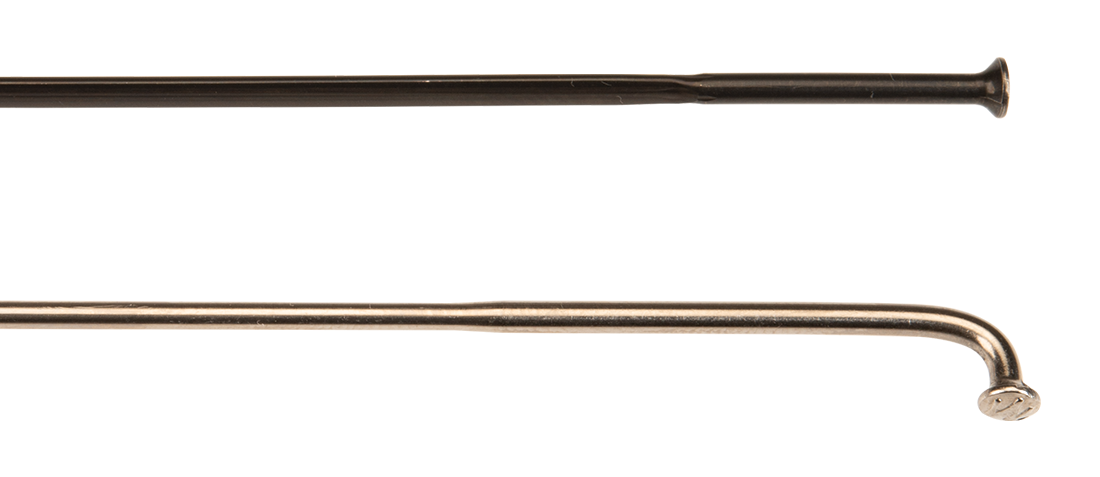
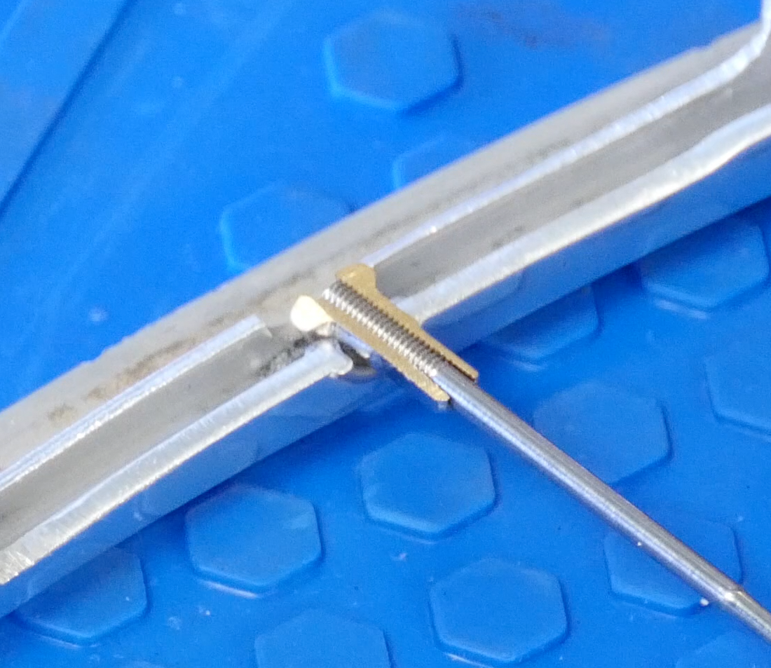
It is important to use properly-sized spokes when building a wheel. Spokes that are too short can be identified by a lot of visible thread at the nipple. This is an indication of poor thread engagement, resulting in a weaker connection to the rim. Spokes that are too long can end up protruding way past the nipple. These spokes are likely to rub against the rim strip or rim tape and eventually cause a flat.
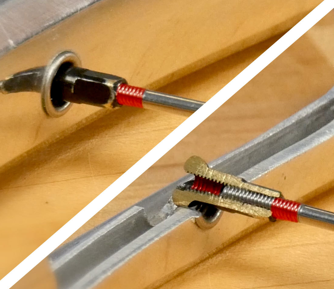
This excess thread is a clue that this spoke is too short for this wheel configuration. In the cutaway, we see that both the spoke and nipple have a lot of unused thread, resulting in poor engagement.
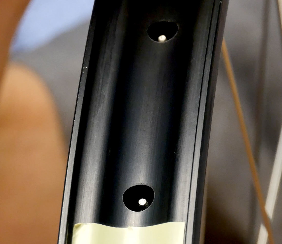
Looking into this rim we see that the thread of the spoke extends far beyond the nipple. This can be bad news for the tube or tubeless setup.
If done correctly, the measurements and calculations done here will result in spokes that are just fully threaded into the nipples. Having the spoke up into the nipple reinforces it, and helps prevent cracking and failure of the nipple, especially aluminum nipples.
Spokes are typically available in 1 millimeter increments, and the proper length is determined by formulas which are based on a series of measurements. These measurements can be fed into online spoke calculators to run the formulas that arrive at a final length.
As you proceed, try to measure accurately. When using a caliper, take measurements to one tenth of a millimeter. This helps prevent measuring errors from compounding along the way. In the end we will round to a whole number for our final spoke length.
Although there are online databases for rim and hub dimensions, not all third-party databases are current or accurate. In some cases, you may find it best to take your own measurements.
The measurements and information you need to determine spoke length are:
- The number of spoke holes in the hub and rim
- The effective rim diameter, called the “ERD”
- Hub flange diameter at the spoke holes, also known as the Spoke Pitch Diameter
- Left and right hub flange spacing relative to the hub center
- Desired cross or lacing pattern
We will walk through how to find each of these measurements. To help keep track of all the numbers, download and print our PDF worksheet HERE.
Effective Rim Diameter
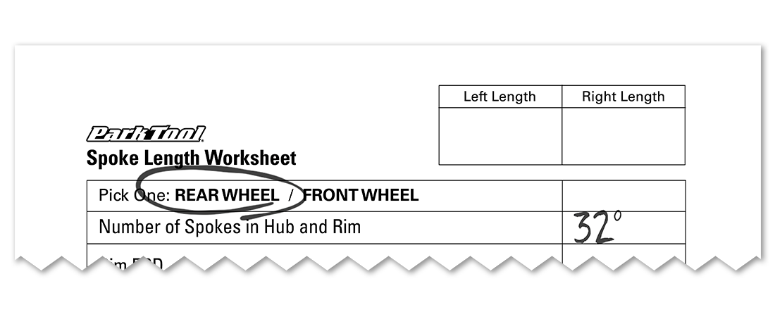
The first consideration for the rim is simply the number of spoke holes. Count them and make sure it matches your hub. Record it on the worksheet.
There are a few ways to measure the diameter of a rim. We are concerned with the diameter as defined by where the end of the spoke sits when it is fully threaded into the nipple. The common term for this is ERD, for Effective Rim Diameter, although a better term would be Effective Spoke End Diameter. This number is sometimes provided by the rim manufacturer on their website or in the included literature. However if you have the rim in hand, it is worth measuring this yourself.
As we are looking to measure to a point inside the rim, there is no practical way to measure the ERD directly — it will require a few measurements, and then some simple math.
This is accomplished with two J-bend spokes with standard slotted nipples, acting as measuring rods. Note that these are not necessarily the spokes or nipples we will use to build the wheel — any identically-sized spokes will do, they only need to be short enough to not meet in the middle.
Determine the length of your measuring spokes with a spoke ruler and record this number. Spokes are typically available in whole millimeter increments.
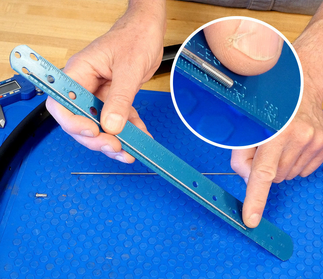
Select a rim hole and engage a spoke through the hole. If you intend to use a rim washer, install it now to factor it in to your measurement. Thread on the nipple to the point where the spoke just comes to the bottom of the slot. This is where we want the spoke to end on a finished wheel.
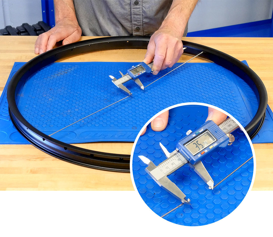
Find the exact opposite rim hole and repeat the process with the other spoke. Pull both spoke heads inward towards the center to seat the nipples. Using the narrow tips of the caliper jaws, measure from inside to inside of each J-bend. Record this measurement to the nearest tenth of a millimeter.
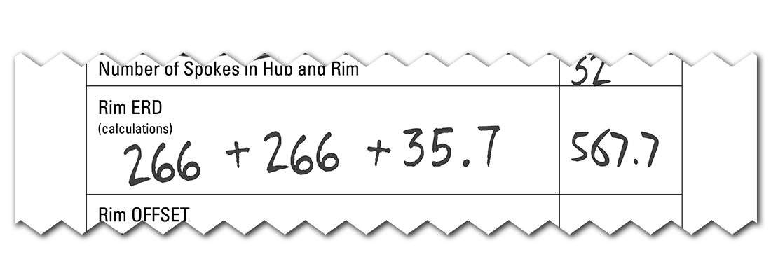
Add all three numbers together:
Spoke 1 length + Spoke 2 length + J-bend-to-J-bend = ERD
Rim Offset
Another aspect of the rim that needs to be accounted for is rim offset, which is a feature of asymmetrical rim designs. Offset is the distance from the rim center to the spoke holes.
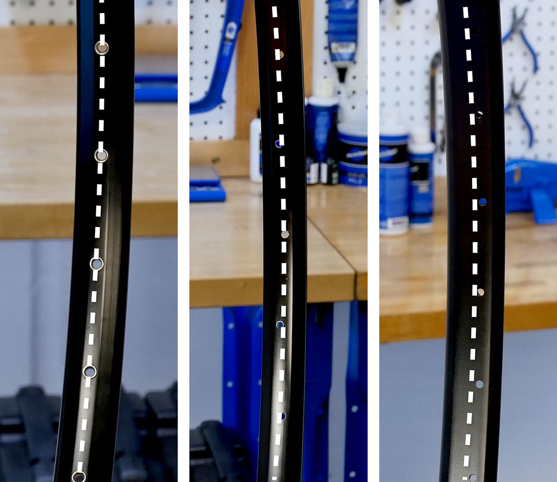
To understand the asymmetrical design, let’s look at some examples below. The first rim shown has spoke holes drilled straight down the middle. It is a symmetrical design and has no offset.
The rim in the center has spoke holes equally staggered left-right-left-right from the center line of the rim. It is also considered symmetrical with no offset.
The rim on the right is an asymmetrical design, with the holes offset from the center of the rim.
On an asymmetrical design, the wider side of the rim should match the side of the hub with a greater flange inset. On a rear wheel, the wide side faces the sprocket side. For front wheels with disc brakes, the wider side faces the rotor side. The purpose of rim offset is to help minimize the average tension difference between the right and left side spokes.
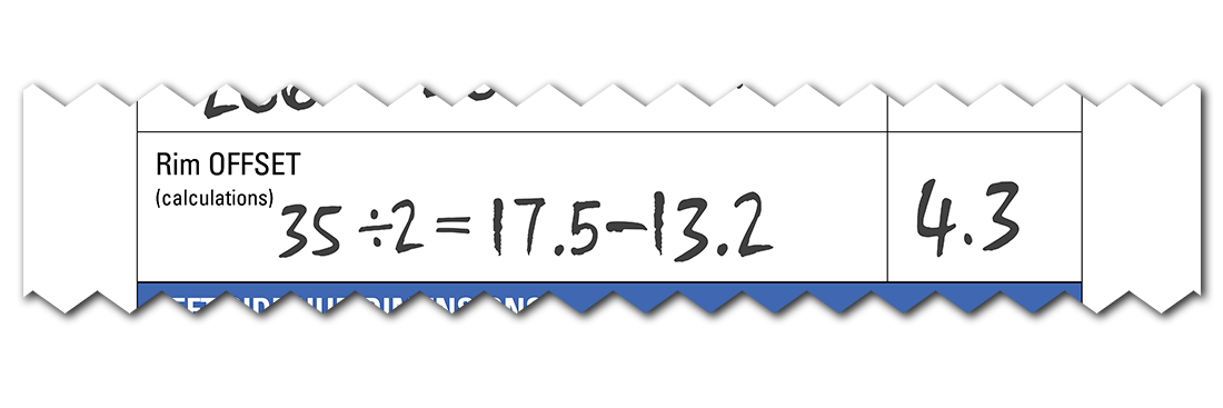
Rim offset may be listed in the manufacturer’s literature. If not: to measure rim offset, lay the rim on a flat surface and measure the width of the rim. Divide this number in half.
Next, measure from the center of the spoke holes to the bench. Subtract this from the center point of the rim.
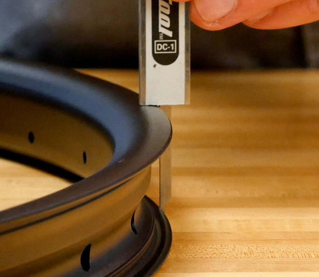
Measure rim width against a flat surface
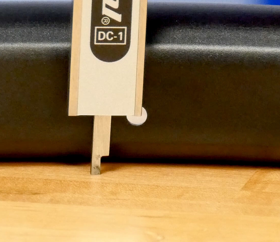
Measure to roughly the center of the spoke hole of the rim
Record this number on your worksheet. If your rim has no offset, enter zero.
Hub Dimensions
The first number we are concerned with from the hub is the number of spoke holes it was designed for. Count these to verify that it is compatible with your rim.
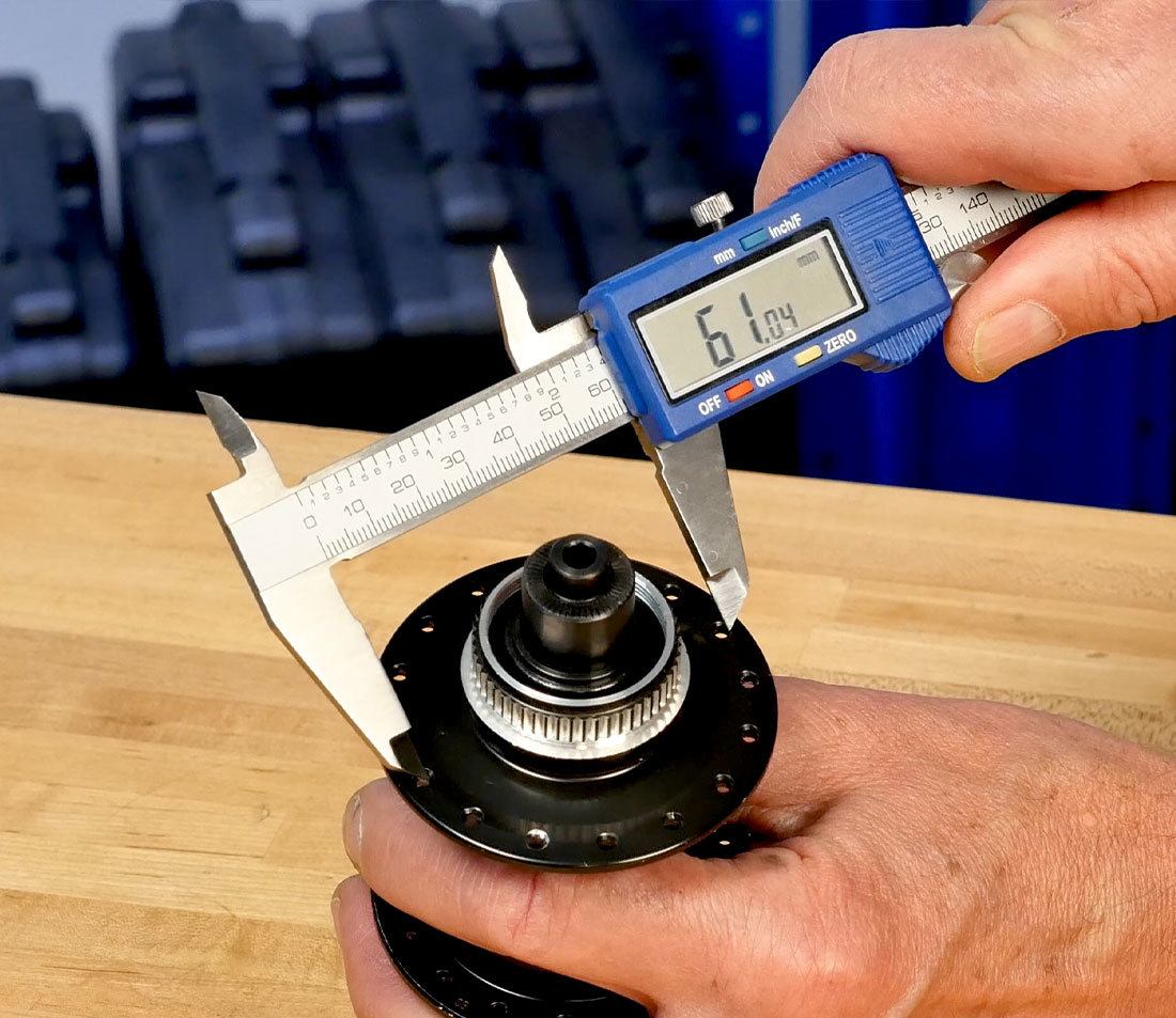
Next, we need the diameter of a circle created by these spoke holes in the flange.
This is sometimes call the flange diameter, but we are not concerned with outside diameter of the flanges — a better term would be spoke pitch diameter.
Using a caliper, measure the distance from one spoke hole to the opposite hole. We are trying to determine the distance from center to center, but it can be difficult to hold the caliper directly in the middle of the each hole when measuring. Try hooking one jaw on the inside edge of the hole and the second jaw aligned to the outside edge of the hole.
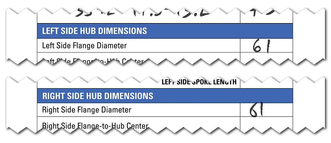
Measure both flanges. Do not assume they are the same. Write down both the left and right side dimensions on your worksheet.
The next measurement needed is the distance from each hub flange to the middle of the hub. This is known as flange-to-hub center. This dimension accounts for varying flange widths as the spoke travels inward to reach the rim.
Flange-to-center is best determined with some measurements and some deductions.
Begin by measuring the over-locknut dimension. This is the width of the hub where it contacts the face of the dropouts. For a open dropout hub, measure to the face of each locknut or end cap. On a thru-axle hub, measure from end cap to end cap.
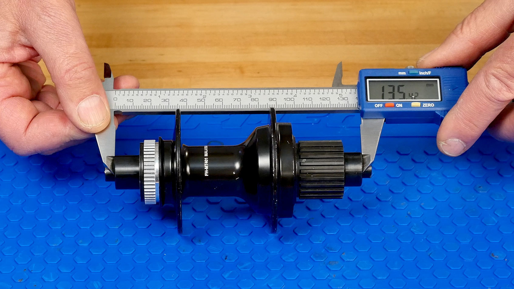
Enter the width on the worksheet. Divide overall hub width by two to find the center of the hub.
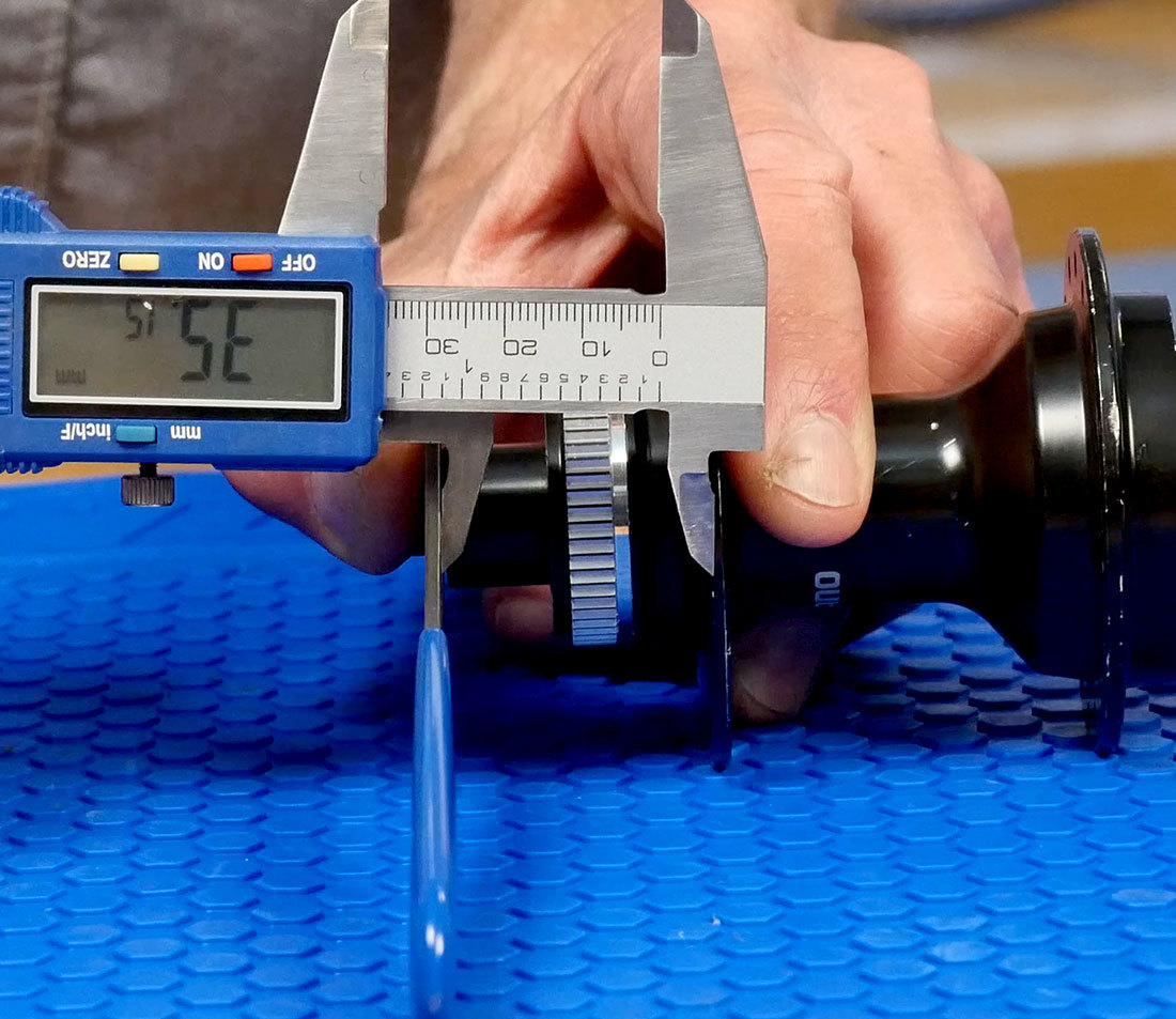
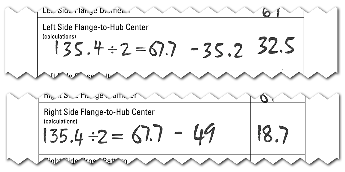
Now, measure from the middle of the right flange to the face of the right side locknut. Use a straight edge against the lock nut or axle end cap to make it easier — this simply extends the line of the face outward. If you are measuring a thru axle hub, a desk can act as a straight edge.
Record your measurement on the worksheet. Deduct this number from the hub center measurement to get your right side flange-to-hub center.
Repeat the process for the left flange. Again, do not assume they are the same.
Many online calculators also have a field for spoke hole size. The default size is usually 2.5 mm diameter. Measure it to be safe, but even if your hub varies slightly, it will not make a significant difference in spoke length.
Lacing Pattern
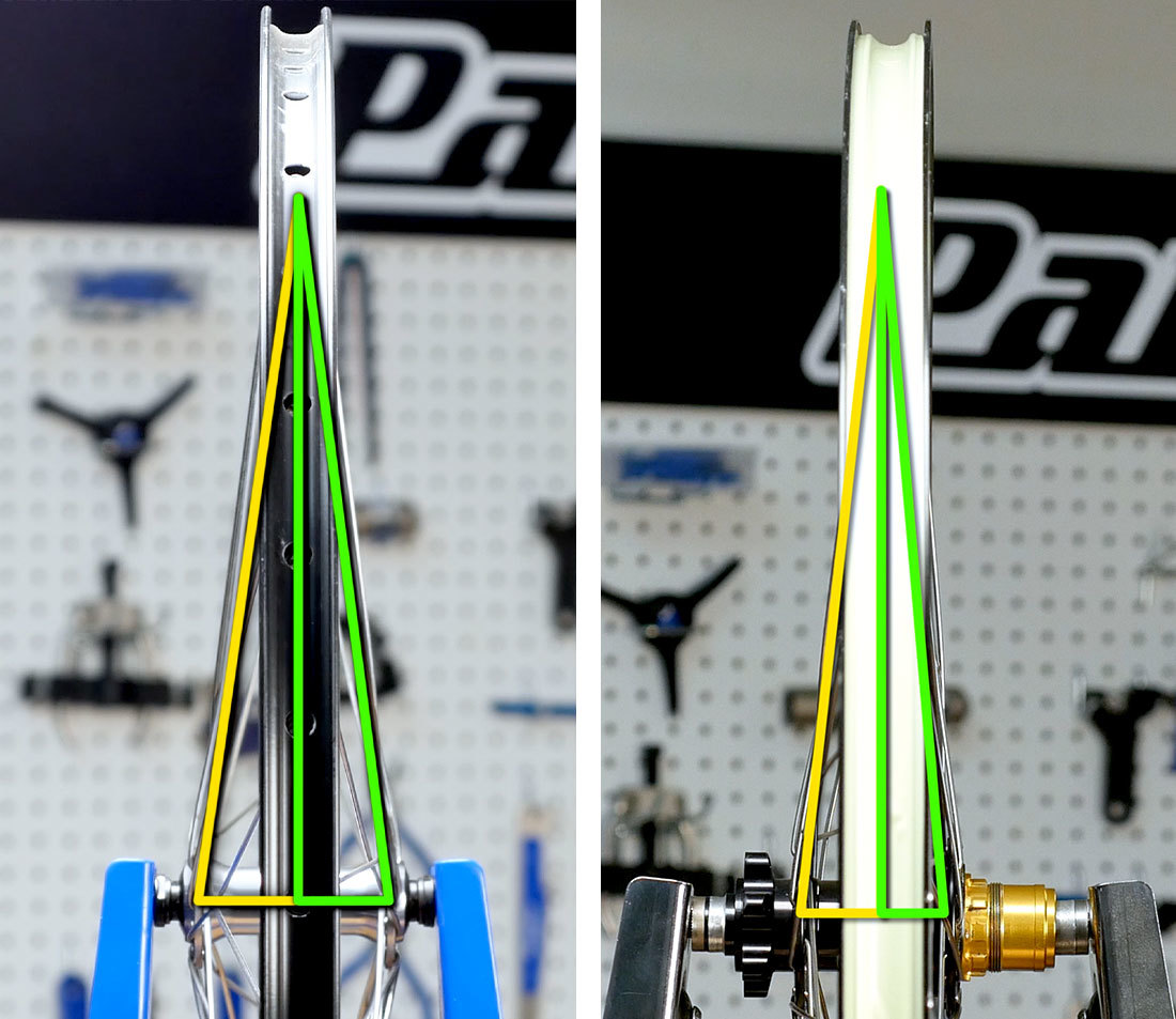
Spoke length is also influenced by the spoke pattern as they radiate away from the hub. The shortest spoke possible would go from the hub straight up to the rim, for a radial (or zero cross) lacing pattern.
If the spokes leave the hub at an angle, they weave across other spokes making a cross pattern. This can be a one-cross, two-cross, three-cross, or even four-cross pattern if the components permit it. Each additional cross requires a longer spoke as the distance from the hub to the rim becomes larger and larger. Once a lacing pattern is decided upon and the correct spokes are acquired, it’s too late to change your mind — a different pattern will require differently-sized spokes.
Differential Spoking
Before entering the data into the calculator, a word about differential spoking. First, let’s define non-differential spoking: when both sides of the wheel are built with the same length spoke. Not different = non-differential. This is most commonly seen on a front wheel with rim brakes, which generally has same flange-to-center measurements for both the left and right sides. Therefore spoke lengths should be the same for both the sides.
Now consider hubs with one flange more inset than the other. For example: on a rear wheel, the drive side flange is pushed inward to make room for the sprockets. Accordingly, the distance from the right flange to the rim is shorter than from the left flange to the rim. When the flange-to-center measurements begin to differ between the left and right sides, we often get the option of differential spoke selections, meaning that different length spokes should ideally be used on left and right sides.
Differential spoke selection is done to create ideal thread engagement on both sides. It does not equal out left and right side spoke tensions.
However, there can be practical reasons to build with one length even when we come up with different lengths from the our calculations. For one, using the same length for left and right side can simply be cheaper. It also simplifies the process of lacing the wheel as you won’t get confused as to which spokes go to which flange side.
Generally, there is a one-to-two millimeter range of acceptable spoke length for a wheel. If you want to build with non-differential spoke selections, and the two spoke lengths are only one millimeter different, select the longer length for both sides, and the wheel will typically be fine. If the two sides are different by two millimeters, you can use the average of the two. However, when you get to a difference of three or more millimeters, it is best to build with two different sizes.
Final Calculations
Once your worksheet is complete with all final numbers, you’re ready to enter them into a spoke calculator.
There are several choices — for our example, we’ll go with spokecalc.io. The process is similar in each, but they are laid out a bit differently:
Choose front wheel or rear wheel. Select hub to make the applicable fields drop down. Enter the dimensions accordingly:
- TYPE: “Classic” here refers to J-bend, and is the default selection
- LEFT FLANGE Ø: Left Side Flange Diameter
- RIGHT FLANGE Ø: Right Side Flange Diameter
- LEFT FLANGE TO CENTER: Left Side Flange-to-Hub Center
- RIGHT FLANGE TO CENTER: Left Side Flange-to-Hub Center
- SPOKE HOLE Ø: Spoke Hole Drilling Size. As noted, 2.5 mm is the most common.
Select rim to input the rim dimensions:
- RIM ERD: Rim ERD
- Offset spoke bed (OSB): Rim Offset
Lacing includes two necessary fields:
- NUMBER OF SPOKES: Number of Spokes
- LACING PATTERN: Cross Pattern. spokecalc.io assumes you are building with the same lacing pattern on each side. If not, simply recalculate with the second lacing pattern and record the length for the appropriate sides.
When you select calculate, you will get a number. As spokes are typically available in whole millimeter increments, round up or down as appropriate to get a whole number.
Once you have the appropriate spokes for your rim and hub, you are ready to lace and build the wheel — see How to Build a Wheel for the complete process.
Next article in this series
How to Build a Wheel View Article