Cantilever Threaded Post Brake Service
This article will review brake caliper mounting and adjustment for cantilever with threaded post style pads. For systems with smooth post brake pads, see Cantilever Smooth Post Brake Service.
Preliminary Information
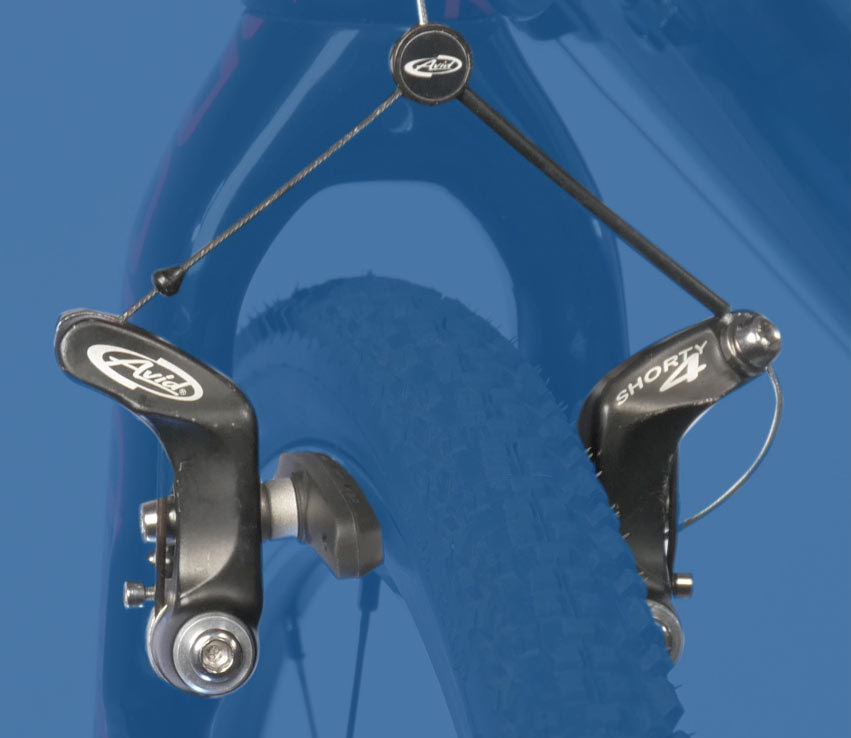
The cantilever caliper rim brake is found on some cross country touring bikes, cyclo-cross bikes, and older mountain bikes. Cantilever caliper arms attach to separate frame pivots on either side of the wheel. The inner-wire attaches to a carrier piece located above the tire. The carrier is pulled upward causing the caliper arms to swing in towards the rim braking surface.
Install Calipers
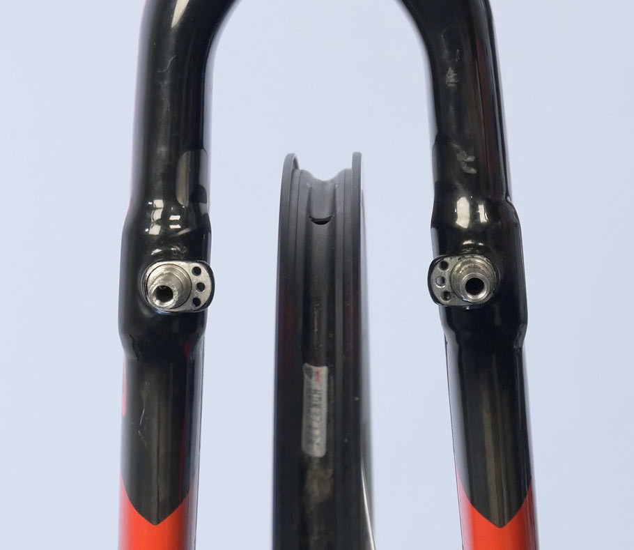
Cantilever caliper arms are attached to the frame or fork on fittings called “braze-ons,” an 8mm diameter by 16mm long stud fitted to the fork or frame. When installing brake arms, grease around the outside of the post.
There are frame and fork designs offering different hole options for the caliper arm return spring: an upper, a middle, and a lower. If the uppermost hole is selected the spring is wound tighter for a more powerful return spring. The lowest hole option winds the spring less and is a weaker setting. Generally, the middle hole is a good place to begin. On the second caliper it’s important to select the same mounting hole you did on the first brake.
Because the mounting bolts are a fairly low torque, it is recommend to add a drop of thread locker inside each boss. The manufacturer’s torque recommendations for mounting bolts is typically between 4–6 Nm.
Spacer Selection
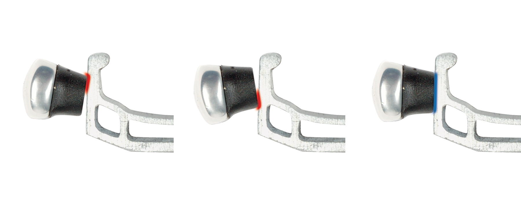
The “threaded stud” style of cantilever brake use a series of convex and concave spacers (washers). On each pad, there will be both a narrow set and a wider set of these spacers. Moving the thicker set from inboard to outboard of the arm will change the angle caliper arm relative to the rim and to the other arm.
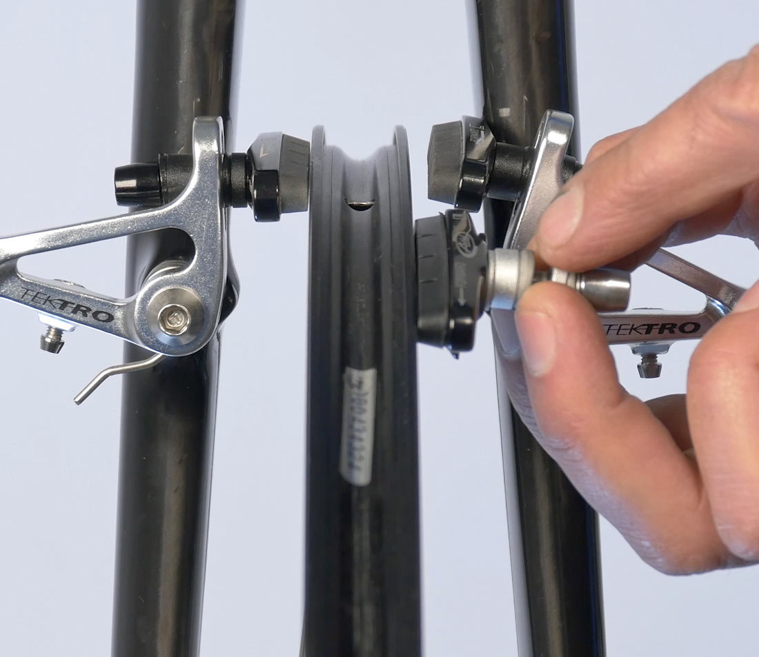
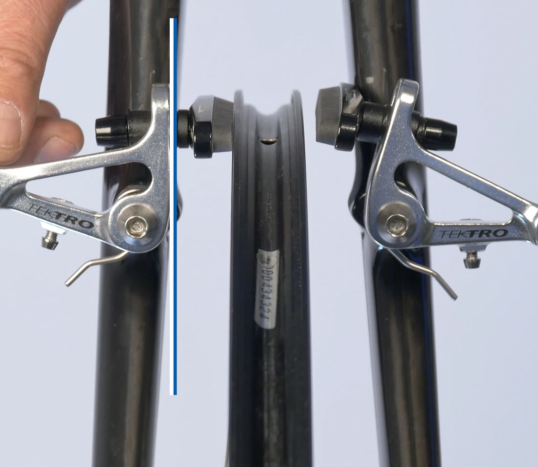
Ideally, the spacers are moved to allow the caliper arm to sit parallel to one another. The provides the best mechanical advantage. In the example seen below, the left caliper from the mechanics point of view has the narrower set of spacers inboard. The right caliper has the wider set of spacers inboard but the arm is now beginning to sit angle outward. For this fork and this brake, it is better to have the narrow spacers inboard.
Good mechanical advantage
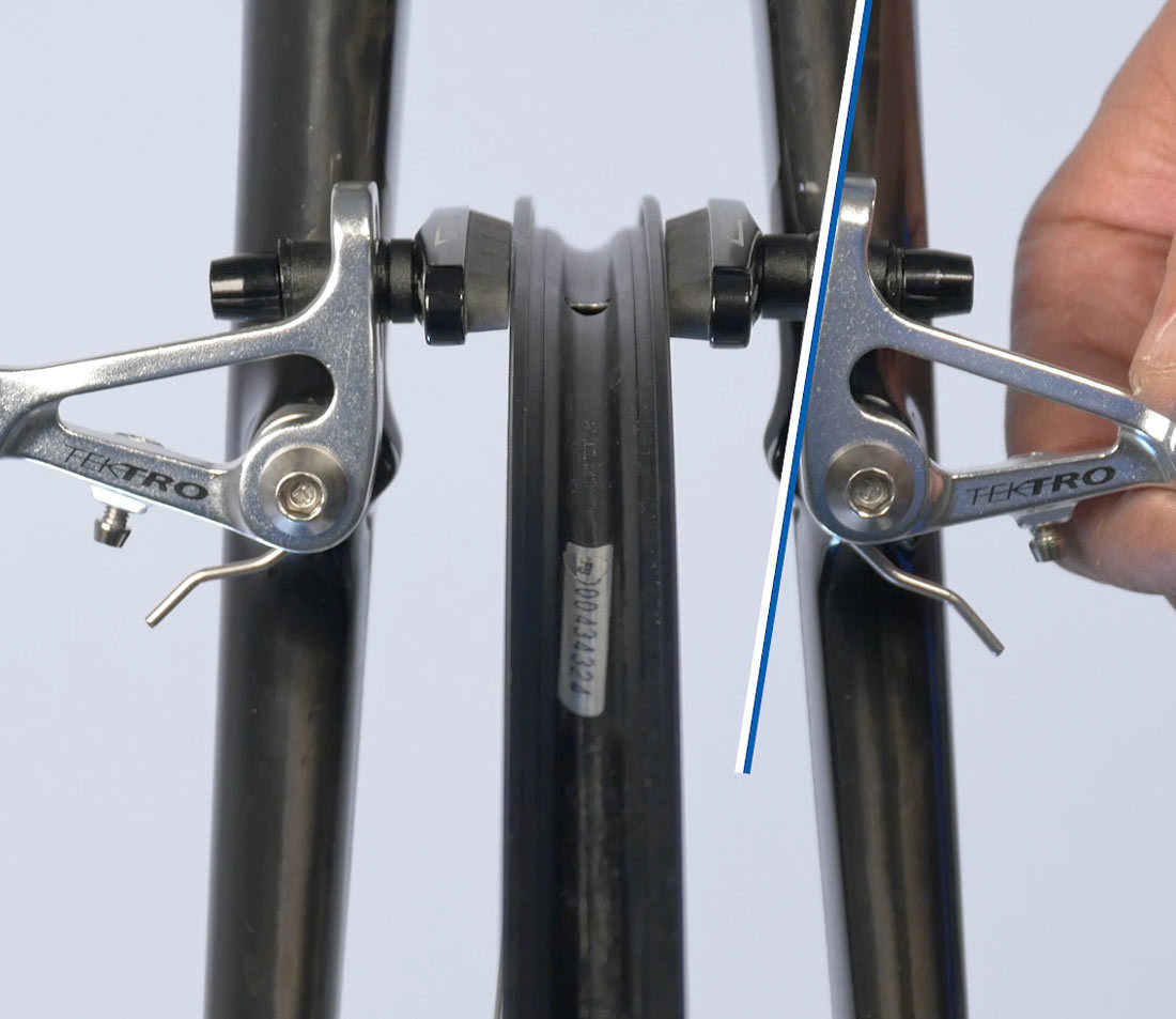
Poor mechanical advantage
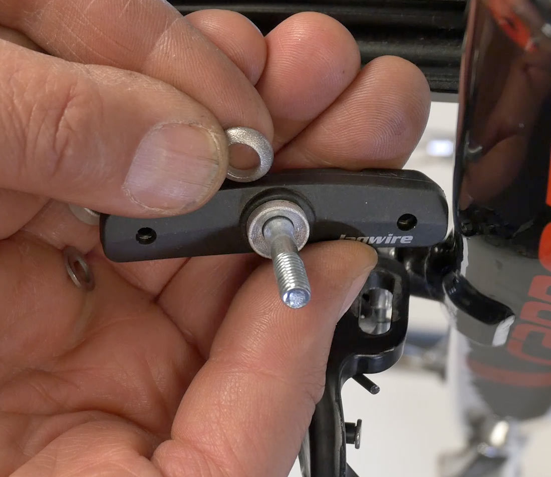
To move the spacers, begin by loosening and remove the brake pad nut. Note orientation of current spacers. The convex side of one spacer should be facing the concave side of the adjacent spacer. The flat sides of the spacers will go against either the brake arm or the lock nut.
Install Straddle Cable & Position Pads
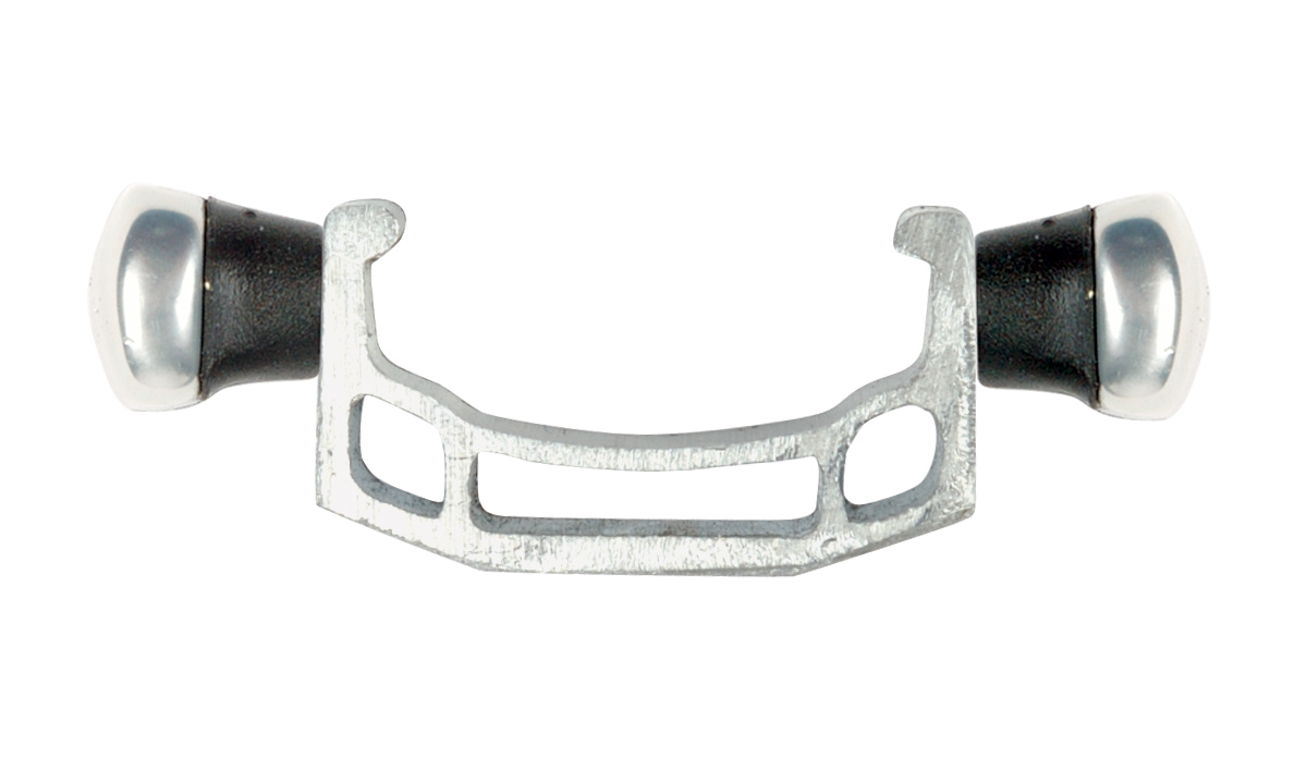
The straddle wire connects to the two caliper arms and is used to pull the arms and pads to the rim. The two common straddle wire systems are a link unit and the straddle wire carrier.
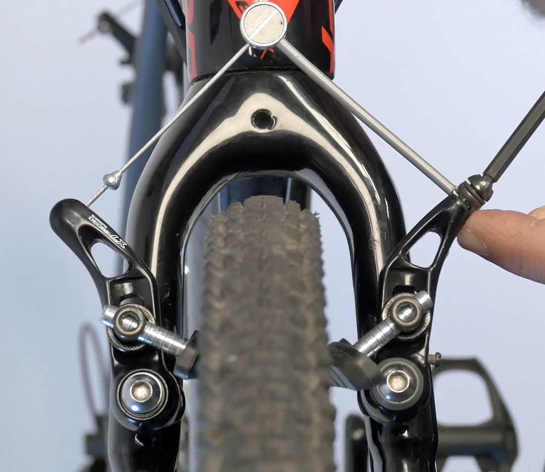
Link unit system connecting left and right caliper arms
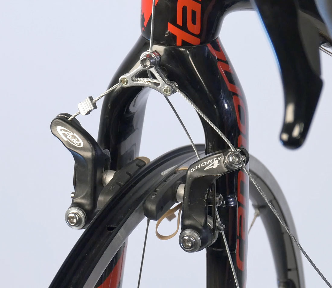
Straddle wire carrier and straddle wire
Link Unit
Link-units are a wire with a head fitted to a center pivot. The wire head fits into one arm and a piece of housing connect to the second arm. The primary wires passes through the head, then through the housing to the second arm, where it is held by a cable pinch bolt.
Pull the caliper arms up to the link unit and inspect the position. The caliper arms are in the best mechanical advantage when they are parallel to one another.
Feed primary wire through link unit
Adjust the cable through the link unit until the arms are parallel
Straddle Wire Carrier
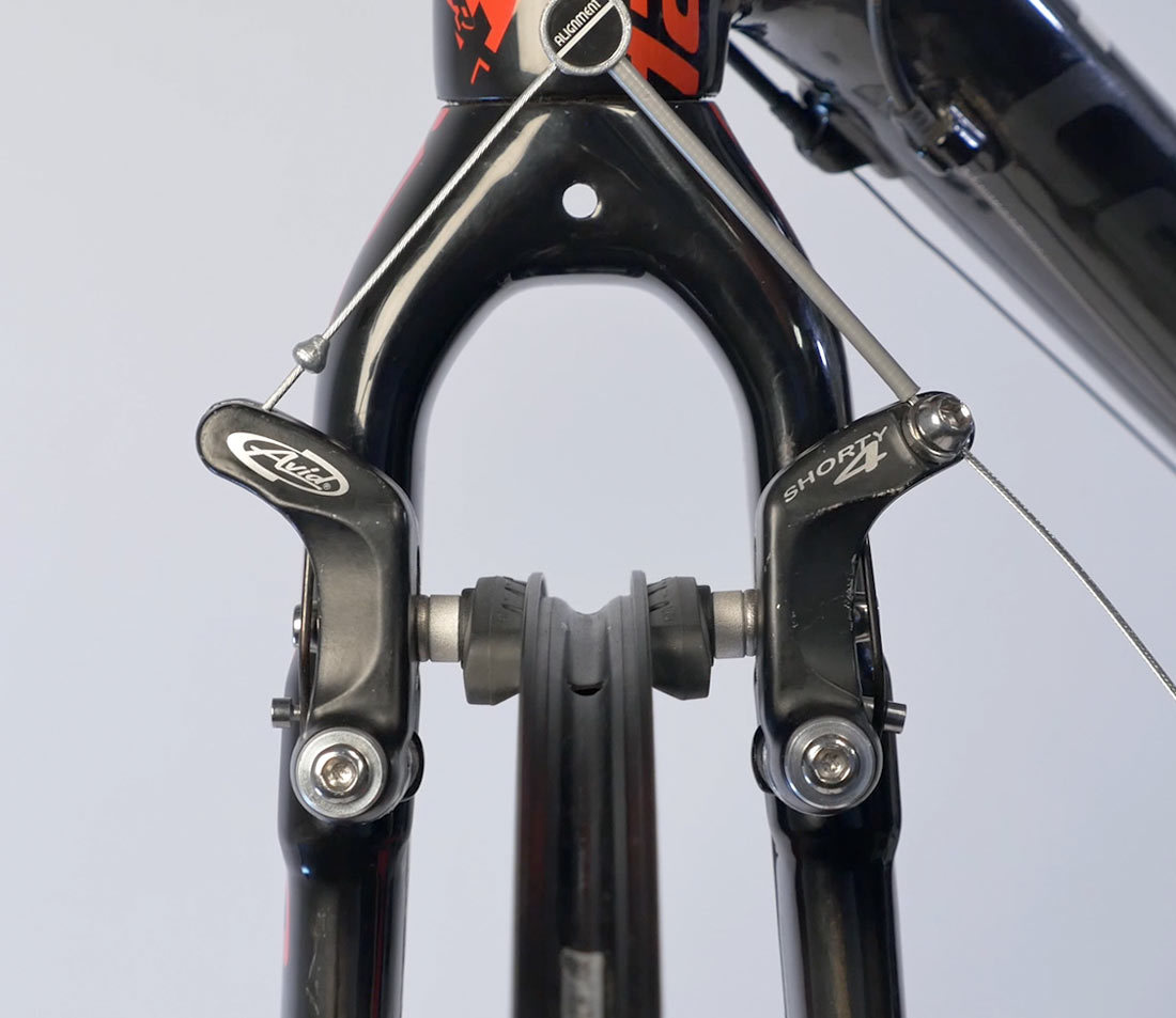
The cable carrier attaches directly to the primary wire from the brake lever. The carrier can be varied in height. If the carrier is secured too far up away from the brake, it will have insufficient mechanical advantage on the caliper arms. If the carrier is secured very low, the straddle cable is going to interfere with anything the tire may pick up, such as mud. The carrier should be no lower than the bottom edge of the fork or the bridge on the seat stays of the bike.
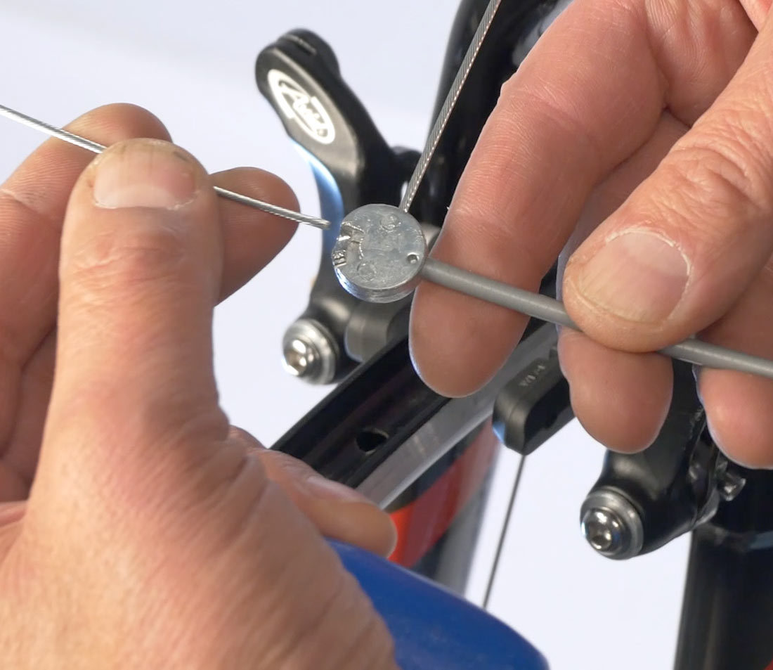
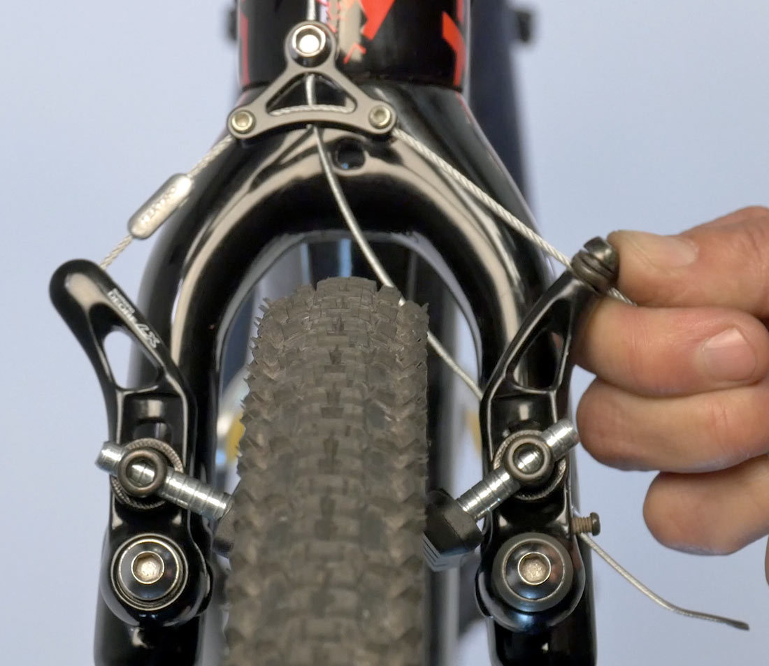
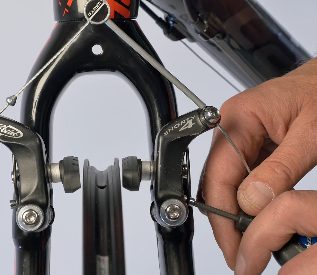
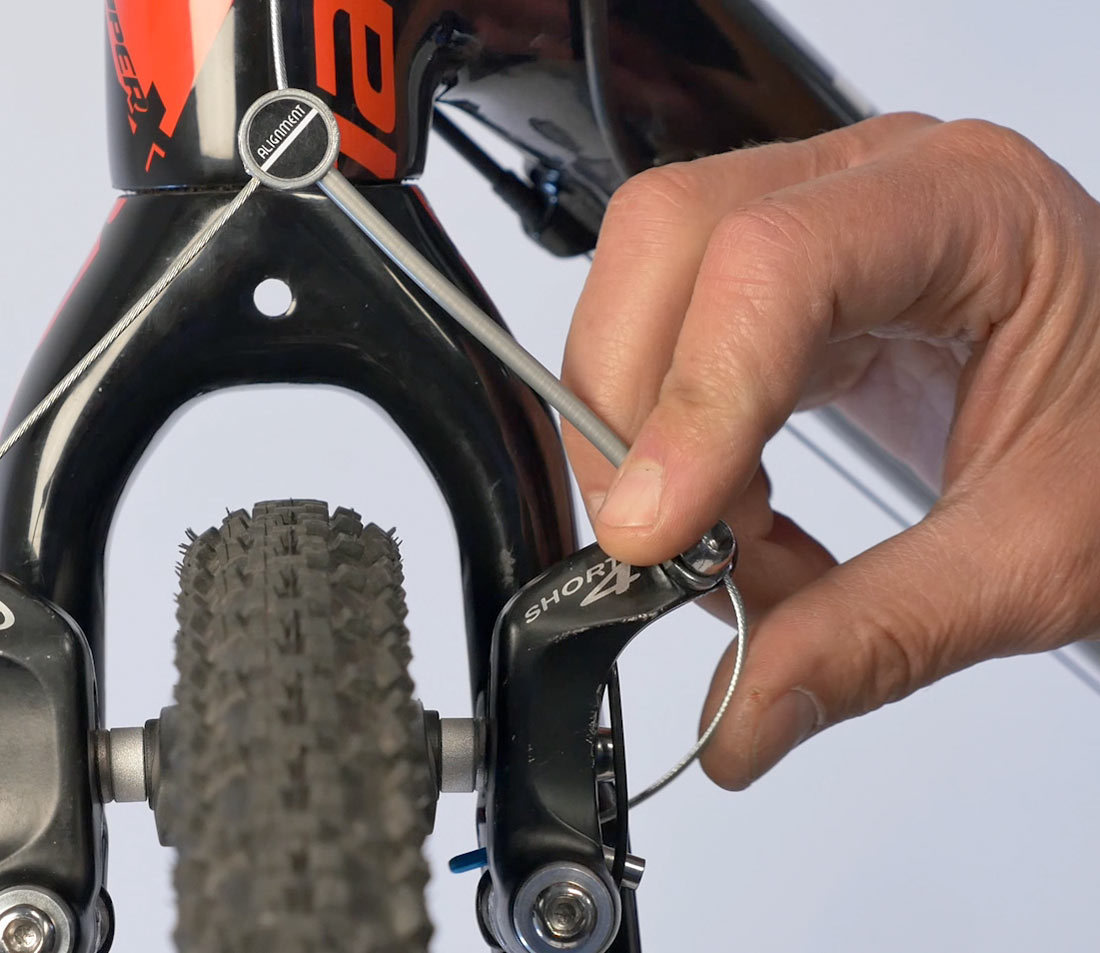
The straddle wire will have a head on one end. Engage the head in one arm and feed the straddle wire through the carrier and through the pinch mechanism.
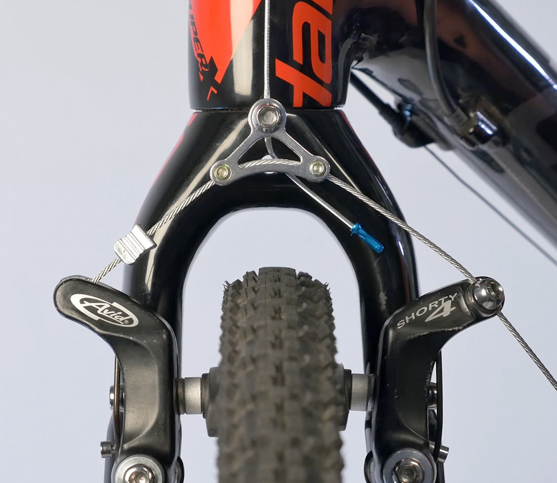
Pull cable through the pinch bolt to adjust the position of the caliper arms. Adjust straddle wire length so the arms are approximately parallel.
Secure pinch bolt and secure to approximately 4–5Nm.
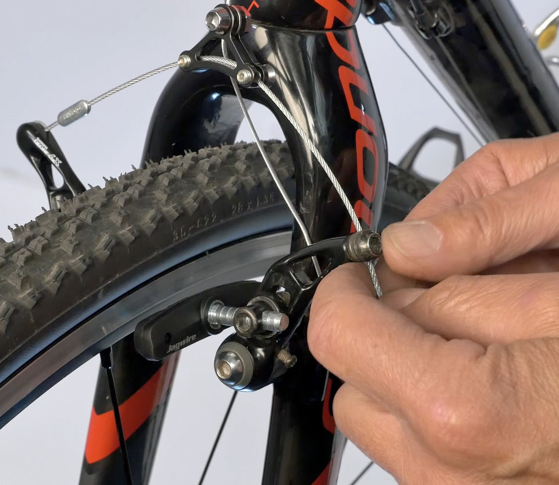
Feed more cable at the pinch bolt to widen these arm until parallel
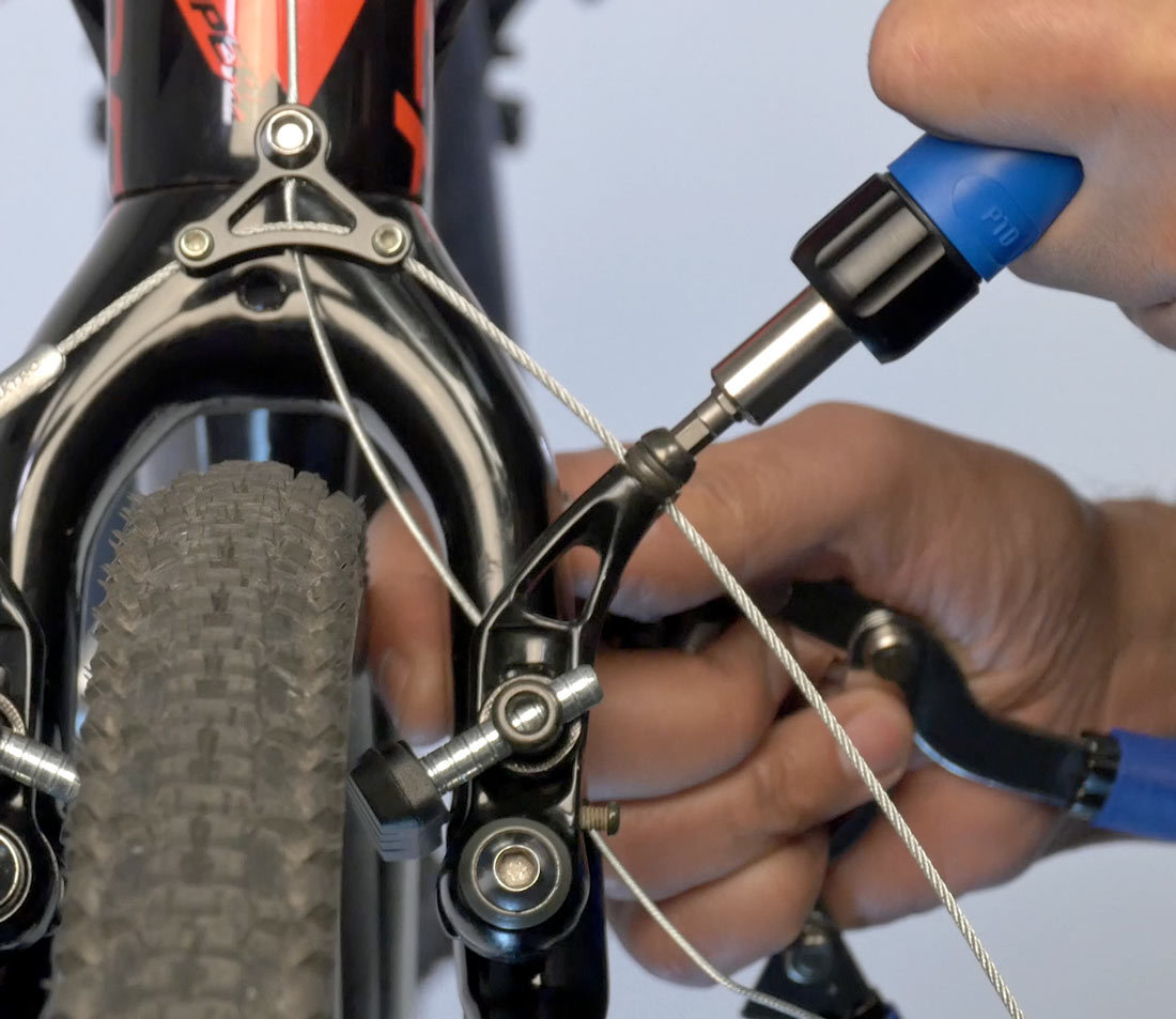
Secure pinch bolt
Brake pads are typically adjustable in several directions. The pad should be correctly adjusted for vertical height alignment, tangent alignment, vertical face alignment and pad toe. Not every brand or model of brake caliper has every adjustment, and sometimes you must simply compromise when setting pads.
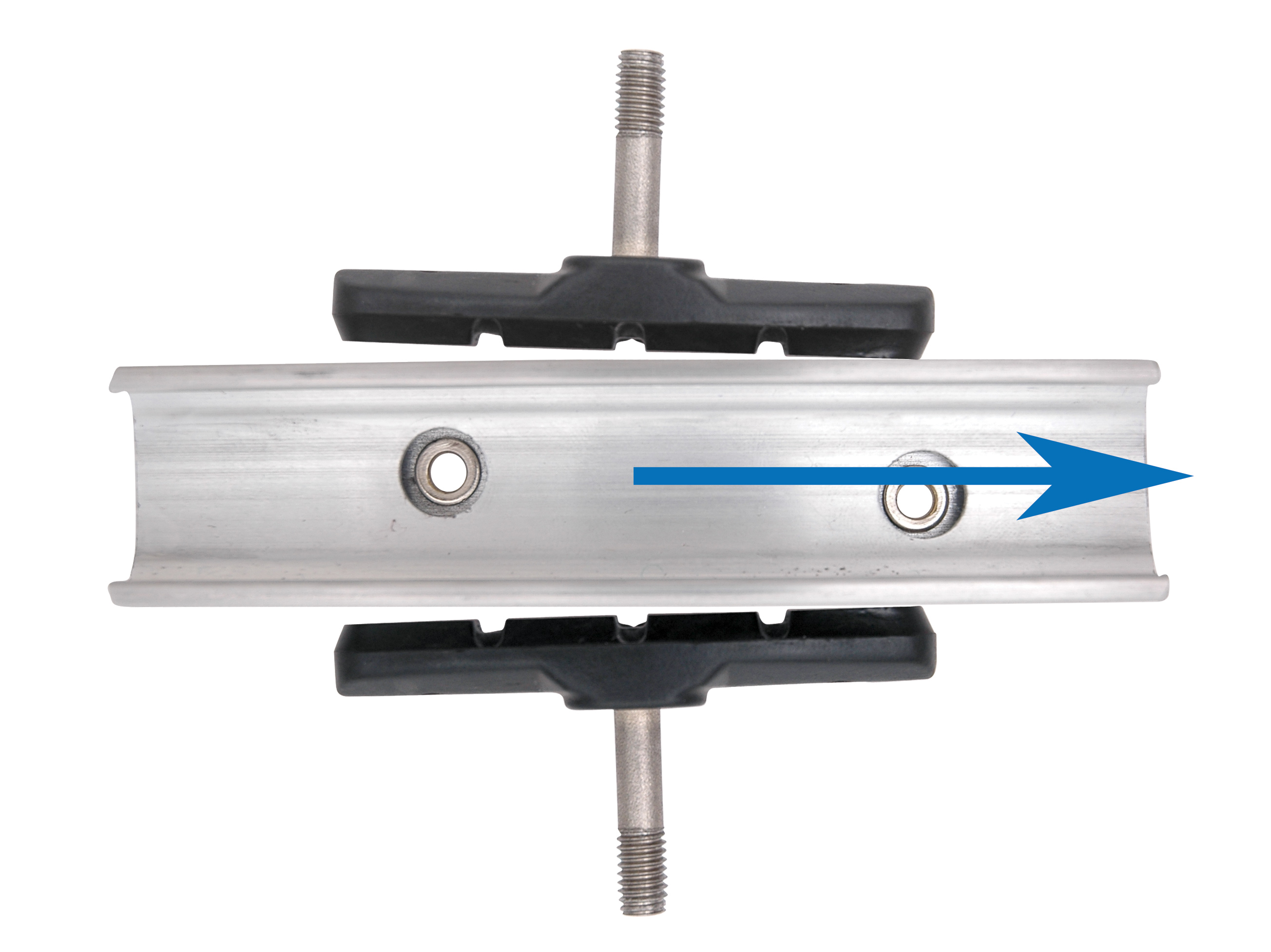
Vertical Height Alignment
This is the setting up and down on the rim-braking surface. View caliper face-on and move the arms, watching the pads move to the rim. Set the pad to the upper edge of the rim-braking surface, but never above the braking surface or where it could strike or rub against the tire. As the pad wears thinner, it tends to move down on the rim braking surface. Setting pads at the top of the braking surface maximizes the amount wear before they need adjustment.
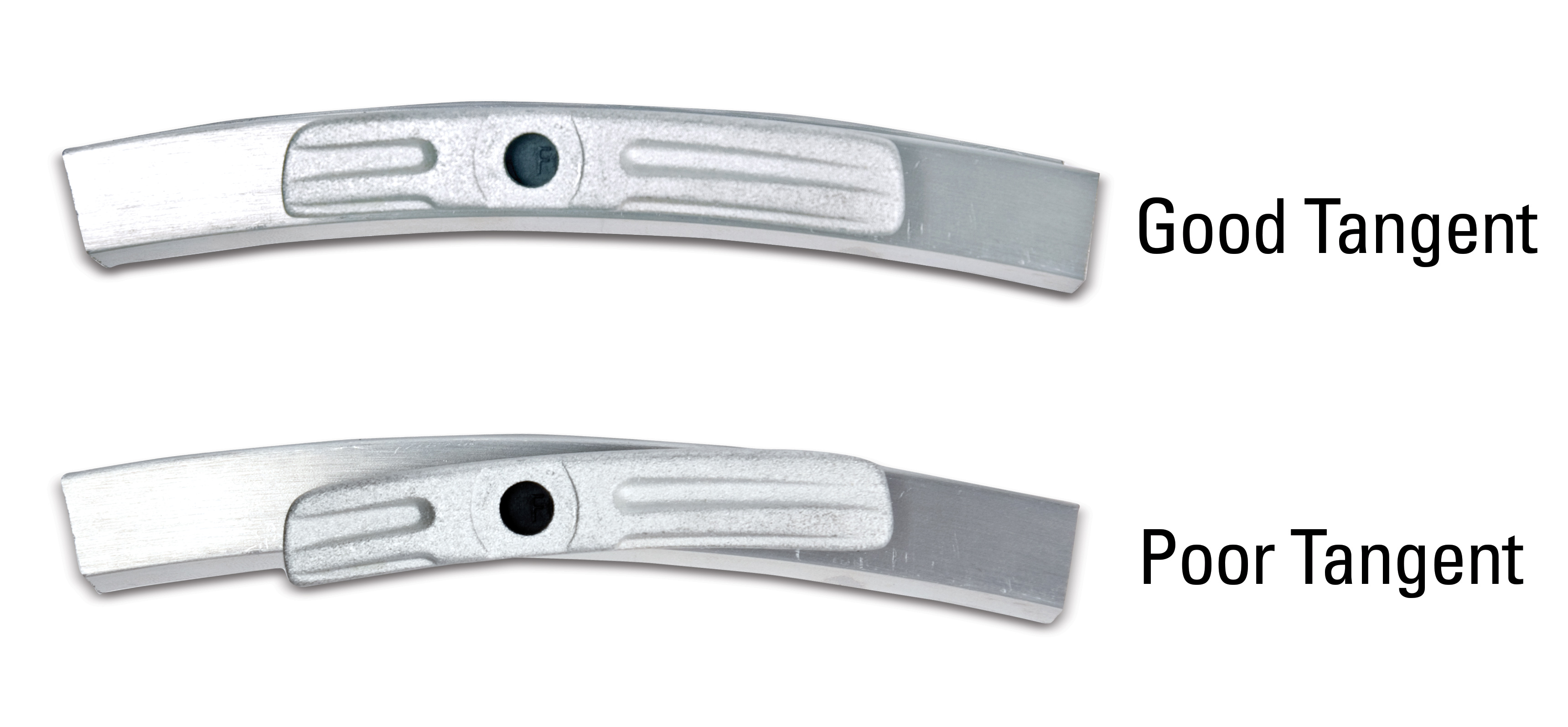
Tangent Alignment
This is the setting of the pad tilt as viewed from the side. The front and back of the pad should be level to the rim. One side should not be higher or lower than the other side. Use care to hold the brake pad to keep it from twisting as the pad is secured.
Vertical Face Alignment
This is the setting of the pad vertical surface relative to the rim vertical surface. The vertical face of the pad should be set parallel to the face of the braking surface.
Pad Toeing
This is the setting of pad angle as it touches the rim. Toeing refers to setting the pad so the pad’s front edge strikes first, which tends to reduce squeal during braking. Caliper arms tend to have play in the pivots and the arms flex when the brake is applied. This may cause squealing in the brake pads. It is simplest to first ride the bike and see if the brakes squeal.
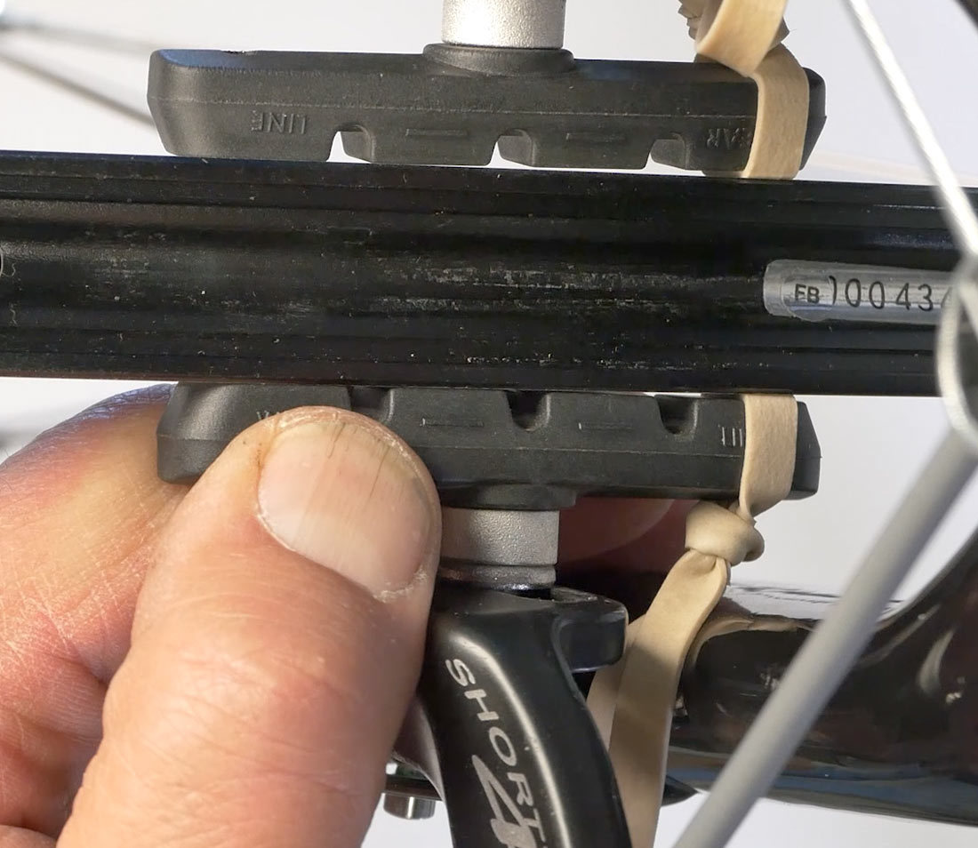
Because of the convex-concave washer system, there can be some self alignment of the pads. It can be useful to use this feature when adjusting pads to the rim. Place a shim at the back of the pad to account for toe, such as a rubber band. The rubber band will push out the back of the pad and create toe in the setting.
Apply some mild force so the arms are up against the rim using a BT-2, or fourth hand, and draw the pads to the rim or pull hard by hand. Secure the cable pinch bolt. When the pad nut is loosened, the pad can be moved for good height, aligned for tangent, and aligned vertically to the rim. The convex-concave washers tend to align to the position of the pad stud. Secure the pad nut and repeat on the other side. Remove the shims, and there should be a slight gap at the back of each pad which is toe.
Set Pad Clearance
The next step is to set pad clearance to the rim, as felt through the lever. Setting the pads too close to the lever will result in a brake that is too tight. This makes the straddle wire difficult to remove when getting the wheel out.
If the brake is set too loose, there will be insufficient cable pull to effectively slow the bike. Use either the pinch mechanism or barrel adjuster to fine-tune pad clearance. Normally the setting on the front would then be duplicated for the same feel on the rear.
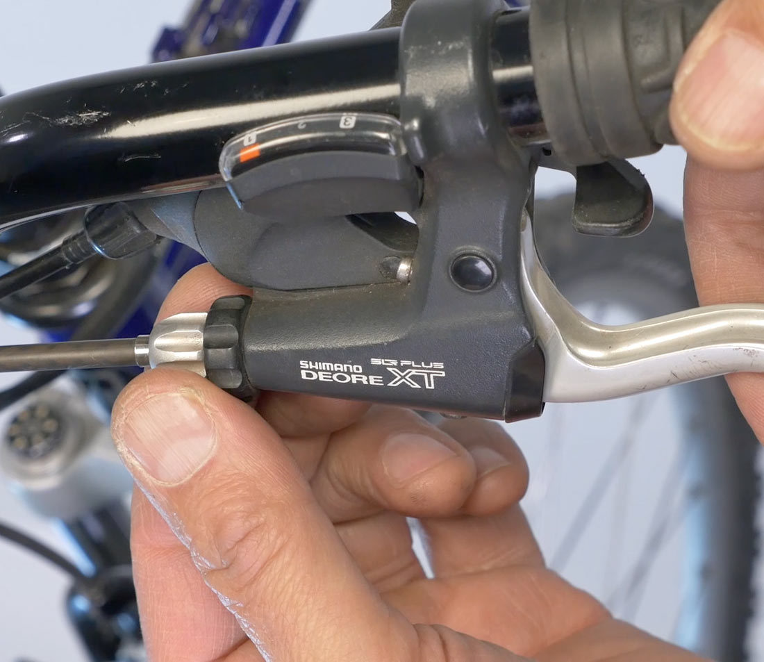
Fine tuning the pad clearance can be done with the barrel adjuster, located either on the brake lever or above the brake arms. Some bikes lack any barrel adjuster and the adjustment is made by adding or subtracting slack at the cable pinch bolt on the caliper arm.
Turning the barrel adjuster counter wise effectively lengthens the housing and takes out slack. Tightening the barrel adjuster inward effectively shortens our housing, relaxes the cable, yielding more pad clearance.
Center Pads to Rim
When the caliper arms are open, the pads should appear equally apart from the rim. However, it is not important that the brake pads strike the rim at the same time.
There is often a centering setscrew for moving the arms left or right. The screws increase the outward pull of the spring. If an arm is too close to the rim, tighten that side centering screw to help pull the pad away from the rim.
If only one arm has a centering screw, either tighten or loosen it to move the one arm either away or toward the rim.
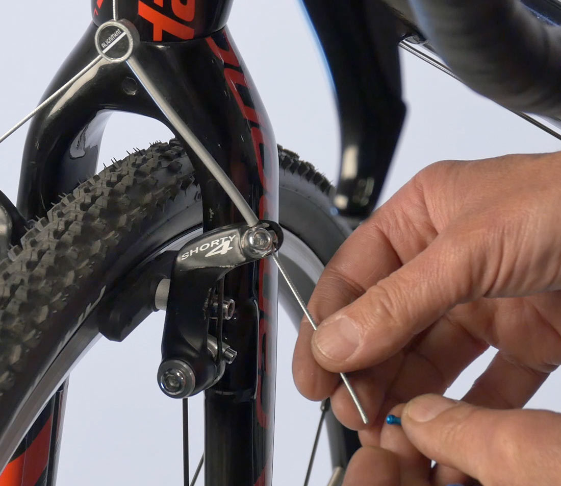
Trim & Cap Cable
The final step is to trim the primary cable and put an end cap on. It’s important not to cut it too short so that there won’t be enough cable to work with in the future, nor should it be so long that it gets caught in the wheel or brakes. Cut the cable long enough that it can be adjusted in the future. Crimp an end cap onto the cable, tuck it back up into the brake in a tidy fashion, and it’s ready to go.
Leave cable long enough for future adjustments
Tuck cable into brake
Related articles
Brake Pad Replacement: Rim Brakes View Article
Brake Housing & Cable Installation: Upright Bars View Article
Brake Lever Mounting & Positioning: Upright Bars View Article