Written by Calvin on September 14, 2009/Calvin's Corner
Campagnolo® Ultra-Torque™ and Record® Group
As manufacturers release new groups and components, there are often new features that require new service procedures. This article will discuss the newer component groups available from Campagnolo®.
The article below will discuss the service and installation features of the following Campagnolo® Record® components:
CRANKSET
The crankset system is an external bearing system. The bottom bracket bearings are mounted to the crank spindle directly. The cups contain no bearings. The bearings are inserted into the cups as the arms are installed. Each arm has one-half of the spindle or axle, and has a “geared” fitting that mates with the opposite arm (Figure 1 and Figure 2).
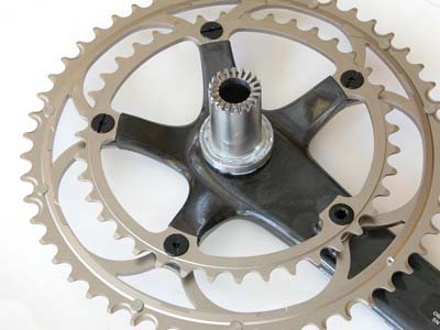
Figure 1
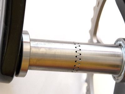
Figure 2
Campagnolo® recommended torque is 310 inch pounds for cups each side. Use the BBT-19 to measure torque. With a hand wrench such as the BBT-9 held approximately six inches from the center of the bearing, apply an effort of at least 50 pounds force (Figure 3).
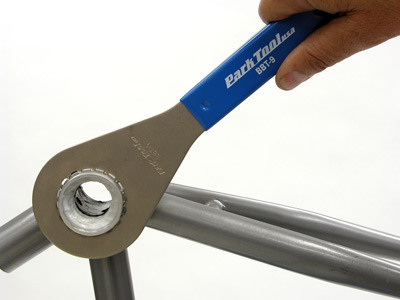
Figure 3
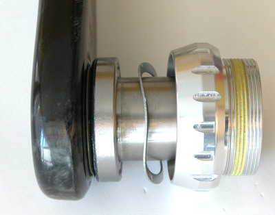
Figure 4
There is a “wavy washer” in the left side cup (Figure 4). This washer is used to account for variations in frame shell widths. For the common “English” or BSC shell the width acceptable width is from 67.2 to 68.8mm. The wavy washer is in effect the “bearing adjustment.” Install both arms and align. Mounting bolt install through the right side axle center. Use a 10mm hex bit on an extension. Recommended toque is 371 inch pounds (Figure 5).
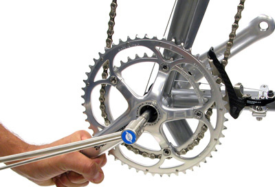
Figure 5
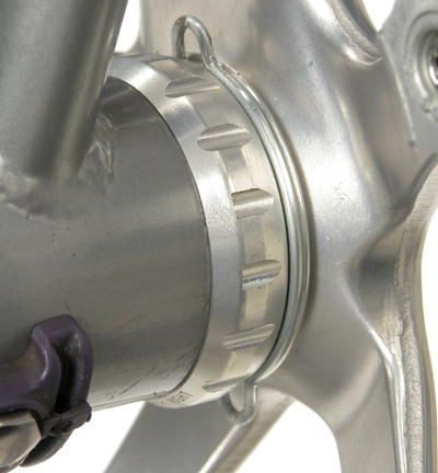
Figure 6
There is a retaining clip that is installed on the right side cup (Figure 6). Install clip using needle nose pliers after arms are installed. Remove the clip before attempting to remove the cranks. No crank puller is used for removal. Loosen and remove the crank bolt. Pull each arm to from cups.
LEVERS
The lever mounting bolt is accessed by pulling the rubber cover forward from the back (Figure 7). Use a 5mm hex wrench such as the AWS-1 to secure lever.
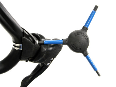
Figure 7
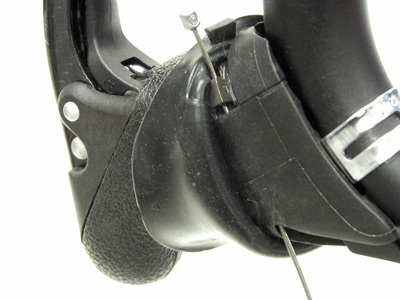
Figure 8
Shift wires install from the underneath the lever body. Pull cover back on lower portion of lever to expose wire entry and exit holes (Figure 8).
Brake wires feed through the top of the brake lever. Pull back on the lever and look for the cable anchor pivot (Figure 9). The wire and housing will exist the back of the lever on the inner face.
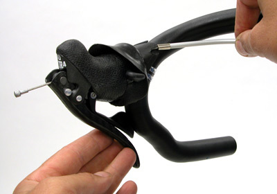
Figure 9
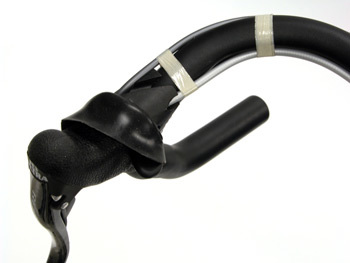
Figure 10
Secure both brake and shift housing to bar before before wrapping bars (Figure 10).
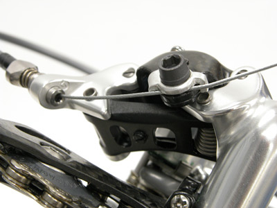 Figure 11
REAR DERAILLEUR
The rear derailleur mounts to the frame using a 5mm hex wrench. Campagnolo® recommend torque is 132 inch pounds. The shift wire routes through the barrel adjuster and under the pinch bolt washer (Figure 11). As in any derailleur, inspect for a grove that will hold the wire. Campagnolo® recommended torque for the wire pinch bolt is 53 inch-pounds.
The Campagnolo® derailleur uses a spring in both the lower and the upper pivots. These springs oppose one another in tension. The “B screw” (body screw) adjustment is made at the lower pivot spring (Figure 12). The lower cage pivot spring uses a “rack and pinion” system to increase or decrease spring tension (Figure 13). Turning the screw clockwise increases lower spring tension. Limit screws use a #2 Phillips screwdriver, such as the SD-2.
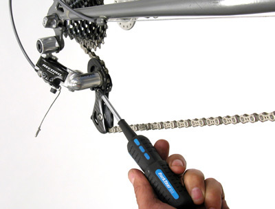
Figure 12
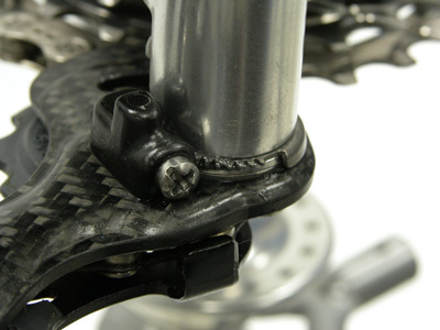
Figure 13
The Campagnolo® rear derailleur is fully serviceable (Figure 14). There are also two spring tension options in the upper pivot spring.
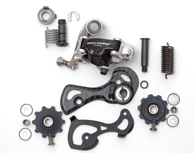
Figure 14
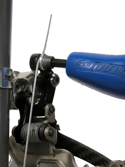
Figure 15
FRONT DERAILLEUR
The front derailleur mounts and adjusts similar to other derailleurs. Route the shift wire under the grove at the pinch bolt (Figure 15).
CHAIN
The Campagnolo® 10-speed chain length is set similar to other systems. The chain closes with a special rivet. When sizing the chain, do not cut the section with original outer plate. Cut the end with the inner plate. Normal service is to clean the chain in place on the bike and replace a new chain and special rivet.
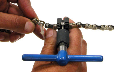
Figure 16
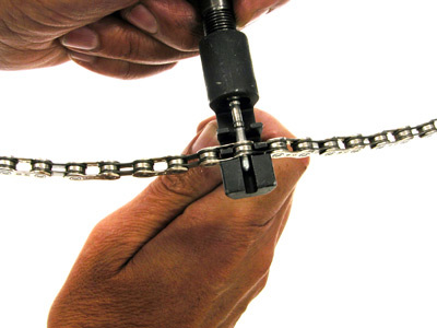
Figure 17
When pressing the special rivet in place, drive the rivet from the inside. The chain tool handle should be away from the mechanic, or toward the spokes of the rear wheel. The special rivet should drive toward the mechanic as you face the right side of the bike (Figure 17). Center the rivet exactly between the two outer plates.
CASSETTE
The cassette cogs will install similar to other makes. The lockring uses the BBT-5 cassette/bottom bracket tool. The cassette cogs are made with a notched spline that will mate at only one place in the freehub body (Figure 18).
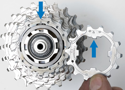
Figure 18
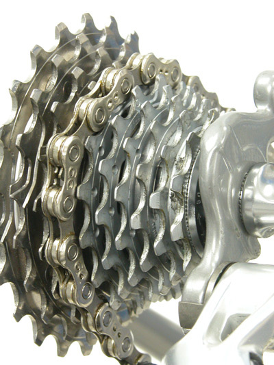
Figure 19
The Campagnolo® cassette cogs are made with “shifting ramps” in the cogs. The chain will ride up these ramps while shifting to the next cog inboard (Figure 19).
CALIPER BRAKES
The Campagnolo® Record caliper brakes uses a dual pivot design for the front caliper, and a side pull design for the rear caliper . Front calipers may be centered with a centering flat on the brake mount stud (Figure 20).
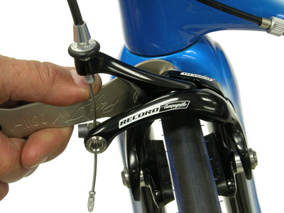
Figure 20
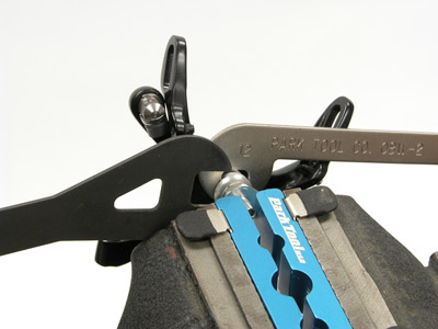
Figure 21
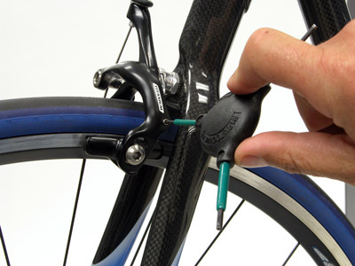 Figure 22
Like any caliper, play may develop in the caliper arms. Calipers must be removed from the bike to adjust pivots. Hold brake mounting bolt using a vise and soft jaws, such as the AV-4. For the rear caliper, use wrenches on the flats of the two mounting bolt nuts (Figure 21). Loosen outer nut and make small adjustments to inner nut. Secure outer nut against inner nut and check adjustment.
The side pull caliper has setscrews in both arms to adjust spring tension (Figure 22). Tension can be changed for feel or as an option to center the brake pads. One side of the front dual pivot caliper uses a setscrew. The dual caliper setscrew can be used to center the brake, or to increase spring tension.
HEADSET
Campagnolo® offers a integrated headset design called Hiddenset (Figure 23). The Hiddenset and the IS integrated headsets do not interchange.
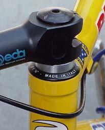
Figure 23
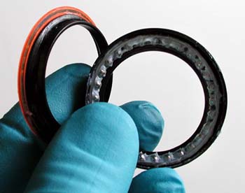
Figure 24
Unlike other “cartridge” bearing systems, the Campagnolo® bearings may be taken apart, cleaned, and re-greased (Figure 24).
The Hiddenset headset frames may be machined if necessary using the HTR-1 and the 761s reamer/facers (Figure 25).
 Figure 25