Bottom Bracket Tapping, Threading, Chasing, and Facing
This article will discuss use of the Park Tool BTS-1 and BFS-1 to perform various machining operations on bottom bracket shells.
Standards & Terminology
- Repair Stand
- Bottom Bracket Tap Set (tapping and facing) BTS-1
- Bottom Bracket Facing Set (facing only) BFS-1
- Cutting Fluid CF-2
- Measuring Caliper DC-2
- Thread pitch gauge
- Degreaser to clean frame after work, such as CB-4 Bio ChainBrite®
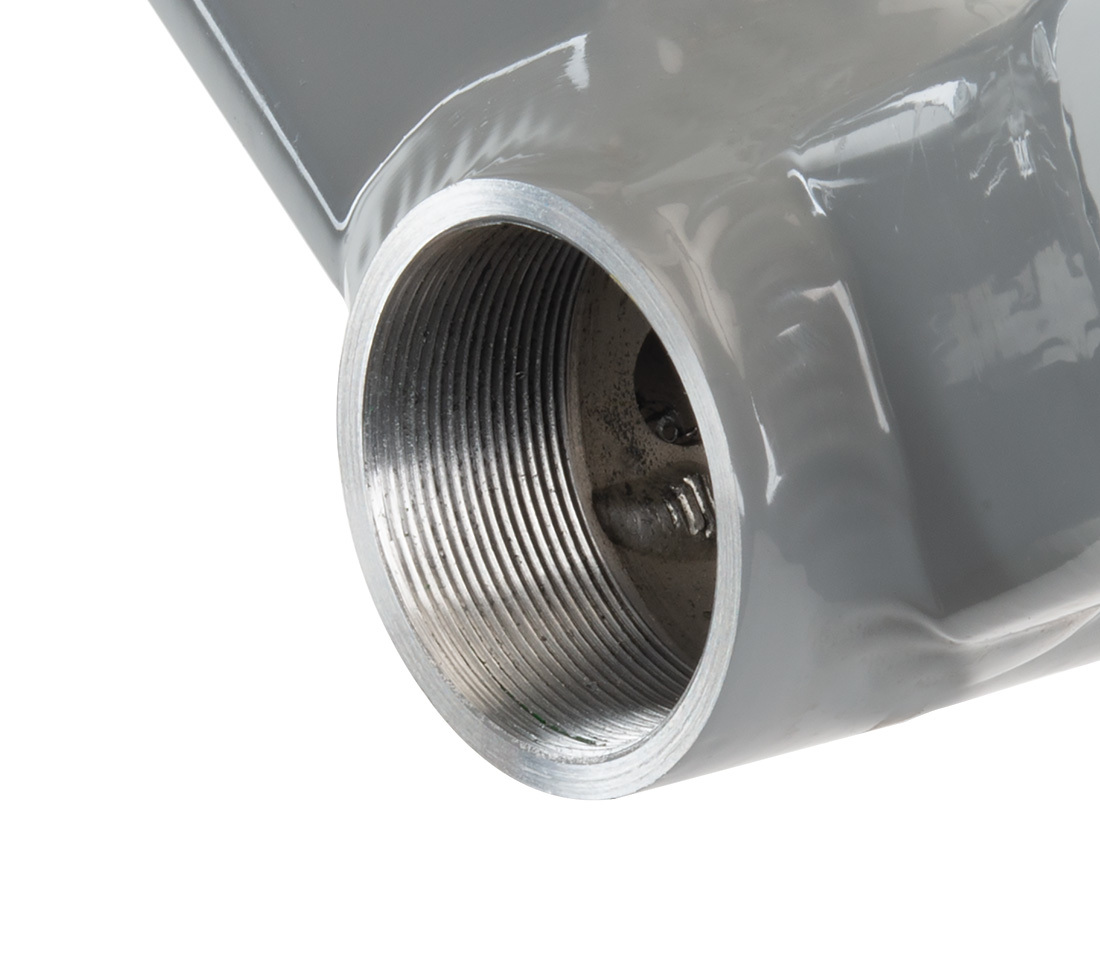
Most bottom bracket shells have an internal thread to accept bottom bracket bearing units from numerous manufacturers. If these threads are not in acceptable condition, they may need preparation. Threads may need realignment, or may have weld splatter from manufacturing that prevents the threading of the bearings. Shells may be out of round due to welding during manufacturing. Additionally, some bearing system benefit from having the faces of the shell square to improve bearing adjustment and bearing longevity. If the shell faces are deformed, and are not parallel to one another, the left and right bearing may not be concentric to one another. Machining the shell face improves concentricity.
The Park Tool Bottom Bracket Tapping and Facing Set BTS-1 will prepare threads and also allow facing of the shell. It consists of two handles, two taps, and a facer. The taps are installed and are left in place as guides for the facer, if facing is desired. Facing is done with hand pressure, which is typically adequate for most bikes.
The common thread norm for the bottom bracket-bearing unit is 1.37″ x 24 TPI. In some countries outside the USA, this is referred to as M35 x 24 TPI. This is because the number 1.37″ has little meaning, and the term 35 mm is common terminology. It has been the habit to name the thread standard by the country of origin, even if the thread is no longer used there. French manufacturers, for example, now use the ISO standard, but the M35 x 1.0 is called “French” threading. The following is a table of threading used in bicycle bottom brackets:
| Bottom Bracket Thread Name | Nominal Thread Description | Cup Ouside Diameter | Shell Inside Diameter |
|---|---|---|---|
| ISO/English | 1.37″ x 24 TPI Park Tool tap part number #691 (non-drive) #692 (drive) |
34.6–34.9 mm Left-hand thread on drive side |
33.6–33.9 mm |
| T47 | M47 x 1.0 Park Tool tap part number #647R (non-drive) #647L (drive) |
~46.9 mm Left-hand thread on drive side |
~45.9 mm |
| Italian | 36mm x 24 TPI Park Tool tap #693 (two required) |
35.6–35.9 mm Right-hand thread both sides |
34.6–34.9 mm |
| French (obsolete, rarely seen) |
M35 x 1.0 | 34.6–34.9 mm Right-hand thread both sides |
33.6–33.9 mm |
| Swiss | M35 x 1.0 | 34.6–34.9 mm Left-hand thread drive side |
33.6–33.9 mm |
| Whitworth (Obsolete, found on older English 3 speeds) |
1 3/8″ x 26 TPI | 34.6–34.9 mm Left-hand thread drive side |
33.6–33.9 mm |
IMPORTANT NOTE: The common ISO/English thread standard found on most bikes uses a left-hand thread on the drive side of the bike. The drive side is also called “chainring side,” and is the right side as seen from sitting in the saddle. A left-hand thread on the drive side is done so the cups tend to be self tightening. This may on the surface appear counterintuitive, but because the ball bearings are rotating, the load direction of pedaling is reversed. The taps of the BTS-1 and the threaded bushings of the BFS-1 are marked for thread direction with LH, for left-hand, and RH for right-hand. These markings DO NOT refer to side of bike. Some bottom brackets are marked with LH and RH that do refer to side of bike. Always check the slope of the thread if in doubt.
Tapping and Facing with the BTS-1
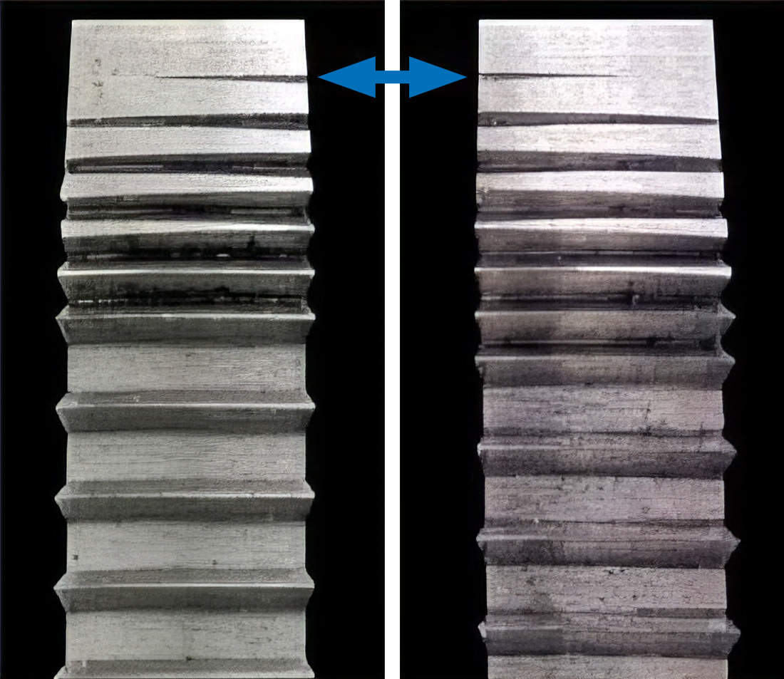
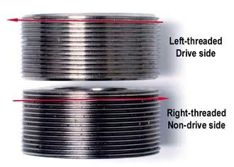
The image below shows the bottom bracket taps in left-hand thread and right-hand threads. Notice the arrow pointing at first section of each tap. A right-hand threaded tap begins with the lead thread on the right. A left-hand threaded tap begins with the lead thread on the left.
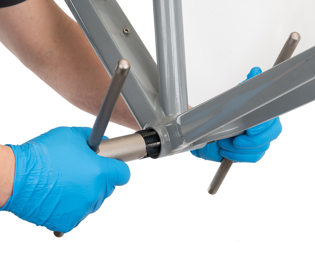
Turn one tap until the tap is recessed in the bottom bracket shell. Turn the tap in slowly—turn, then back slightly, then advance again. This breaks the chip created by the cutting teeth. Add more cutting fluid each full turn.
Turn the other tap until the tap is recessed in the shell, repeating the process above.
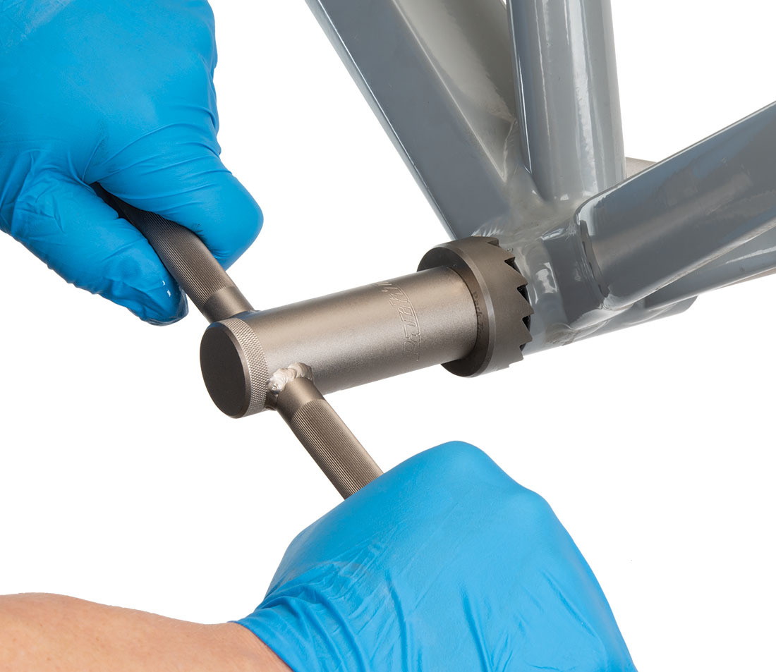
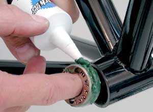
If facing the shell is desired, remove one tap handle by pulling outward on the handle. Install the facing tool #690 onto the tap handle. Apply cutting fluid to the face of the cutter, and bring it gently into contact with the shell.
Hold in middle of handle, and turn CLOCKWISE while applying pressure. DO NOT rotate facer counter-clockwise, this may dull the facer teeth.
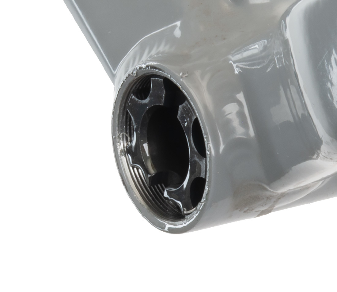
Pull back on the handle after several turns and check progress. When cut metal appears in a complete circle, facing is finished. The facing cut is complete when there is a flat milled surface in a 360-degree circle around the shell face. The full width of the shell face does not need to be cut. Continue cutting if necessary.
After the cut is complete, turn the facer gently against the shell to remove burrs.
Remove second handle, install on other side and repeat process on second face.
Remove facer from handle and install handle into tap. Remove both taps. Use care to unthread taps simultaneously to prevent thread damage.
Clean taps, and clean inside of bottom bracket shell using a brush.
Facing with the BFS-1
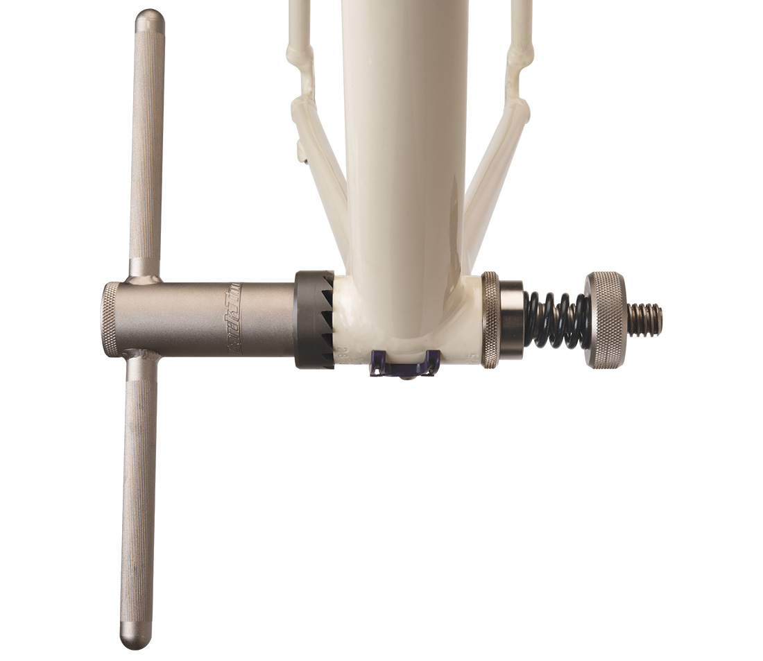
The Park Tool Facing Set BFS-1 consists of one handle with spring pressure system, two threaded bushings, and one facing cutter. It is intended for facing only. Threaded bushings require a properly threaded bottom bracket. If the threaded bushings do not thread into the shell, the shell must be tapped. The spring pressure system on the BFS-1 allows much greater load to be applied during facing, and will remove material in a shorter time as compared to the hand pressure of the BTS-1 system.
The BFS-1 uses two threaded bushings that are installed inside the shell. The internal threads must be acceptable in order for the threaded bushings to fit. Use the BTS-1 if the threaded bushings do not thread in place.
The image below shows the left-hand thread and right-hand threaded bushings of the BFS-1. Notice the thread slopes at an angle. The left-hand thread direction slopes upward to the left. The right-hand thread direction slopes upward to the right.
If there is a left-hand threaded guide, install into the drive side (right side) of bike. Use handle of BFS-1 to thread bushings until both are recessed into frame.
Note: If threaded bushings are difficult to install, remove and tap shell with BTS-1. Threaded bushing must be recessed into bottom bracket shell.
Place handle with #690 facer through either side. Install on other side washer, spring, keyed spacer, and tension adjusting nut.
Turn handle clockwise only to begin cutting. Increase pressure as necessary by tightening tension adjusting nut.
After making several rotations, loosen the adjusting nut and draw the #690 cutter away form the shell face to inspect cut. See explanation in BTS-1 procedure above for a complete cut.
After cut is complete, loosen adjusting nut and use light-hand pressure at center of handle to remove any burrs left by #690 cutter.
Remove adjusting nut and remove handle from shell. Remove #690 facer and use handle to threaded bushings from shell. Clean frame of any cutting fluid.
Clean facer, threaded bushings, and inside of bottom bracket shell. Do NOT use compressed air to clean metal shavings.
NOTE: All cutting tools will eventually require resharpening. With use, the cutting edge will dull. While there are many variables that play a role in how long a cutting tool will stay sharp (e.g. technique used, amount and type of lubrication used, type of material being machined, etc.), in general, have the tool resharpened once a year.
Related articles
Basic Thread Concepts View Article
Bottom Bracket Service: Adjustable Cup-and-Cone View Article
Bottom Bracket Service: BB30 Adapters View Article
Bottom Bracket Removal & Installation: Threaded View Article
One-Piece Crank & Bottom Bracket Service View Article
Bottom Bracket Service: Power Torque™ View Article
Crank & Bottom Bracket Removal & Installation: Campagnolo® Ultra-Torque® View Article