Chainline Concepts
This article will discuss the concept of chainline. See also related article on frame alignment.
Basics
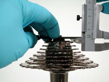
- Measuring caliper such as the DC-2
There are two related aspects to the term “chainline.” First, chainline can be defined as the position of the cogs or chainrings relative to the center line of the bike. The bike center line is an imaginary plane running front to rear through the middle of the bike. For example, a front crankset and/or front derailleur might be designed to have a chainline of 47.5 mm. This means it will work best when the middle of the crankset is 47.5 mm from the middle to the bike center line.
The other aspect of chainline refers to the relative position of the front and rear cogs to each other, without regard to the bike centerline. This is called “effective chainline.” A bike may have the crankset inward or outward some distance relative to the rear cogset center, regardless of the center line of the bike.
Drivetrain manufacturers generally do not specify “perfect” or exact center-to-center alignment between rear and front cogsets. The front chainrings are often designed be a few millimeters outward relative to the center of the rear cogs. Additionally, drivetrain manufacturers do not generally consider all gear combinations to be “useable.” For example, which may be sold as a “27-speed” with three rings in front and 9 cogs in the rear will not have 27 useable gears. It is likely when the chain is on the smallest ring in front and possibly the smallest two, three or even four cogs in back the chain will rub the side of the middle ring. This should not necessarily be considered a “chainline” error. If the front ring were moved outward until there was no rubbing in these combinations, the result would likely be poor shifting in other gear combinations, such as the largest ring and the larger rear cogs.
Bicycle shops commonly recommend against “cross-chaining” which is using the smallest rear cog with the smallest front ring, or the largest rear cog and the largest front ring. Bicycle chains are quite flexible, and will work well at various other then perfectly straight. Cross-chaining is primarily an issue when the chain hits the front rings. As a simple rule, if a gear combination causes a rubbing problem, avoid that gear.
Front Chainring Position and Bottom Bracket Length
The front chainrings should to be within a certain distance of the bicycle center line. If the rings are too far in or too far out from the frame, the front derailleur may not shifting properly. The position of the front rings is in large part determined by the length of the bottom bracket spindle. Many bottom bracket spindles are specified with a certain chainline number, such as 47.5 mm or 50 mm. Spindles are also specified by spindle length, which is simply the length end-to-end. As an example, a particular bottom bracket may be specified with a 47.5 mm chainline, and a 113 mm spindle length. A crank arm designed for use with this spindle will have the middle of the crankset 47.5 mm from the bike center line.
Manufacturers often specify both spindle length and chainline, as both concepts are related. For example, cartridge bottom brackets may come in various spindle lengths. For example, the 118 mm is 5mm longer than the 113mm bottom bracket. The chainline of the 118 mm of this particular model is 50 mm. The 113 mm spindle has a chainline of 47.5mm, or 2.5mm smaller. This is because in this case the 5mm shorter spindle is split between evenly between the left and right sides. However, a different model of spindle may be available in 109.5 mm or 118.5 mm lengths. The difference in spindle length is 9 mm. The chainline of the 109.5 is 43.5 mm, and the chainline of the 118.5 is 45mm. The difference between the spindles in not even split between the two different lengths.
Often, the combination of crank and spindle determine chainline. This is especially the case for the square-type spindles because the exact fit inside the square fitting of cranks varies between brands and even between arms of the same model. It is sometimes necessary to simply guess at a bottom bracket for a bike, install the crank and then measure the results. The results will then let you know if a longer or shorter chainline spindle should be installed.
It is often useful to know the existing position of the front rings relative to the bike center plane. However, it is difficult to take a direct measurement from the center of the bike to the center of the front rings. It is necessary to take several measurements, and then determine chainline by adding or subtracting the measurements.
The accuracy of measuring for chainline is limited by the accuracy of the frame. If the bottom bracket or frame tubing is not centered, the chainline measurements may be off. In our example here, we will assume the frame is aligned and shell is centered. Begin by measuring the diameter of the downtube, and divide this number by 2. In our case, the seat tube is 44 mm, so it is 22 mm from the right side edge the tube the bike center line.
Next, measure the distance from the downtube edge to the middle of the chainrings. On a two-chainring bike, begin by measuring from the largest ring to the tube. Our bike below measure 29mm from the outer ring to the tube. Next, measure the outside-to-outside of the two chainrings, and divide this by 2. The bike illustrated here is 9.8 mm outside-to-outside, making it 4.9mm to the middle. Deduct 4.9 mm from the 29 mm, and it is 24.1 mm from the middle of rings to the tube. Add the 22 mm for the tube-to-center, and it is 46.1 mm from the middle of the crankset rings to the centerline of the bike.
For three chainring bikes, the concept is to find the measurement from the middle of the chainring to the center plane of the bike. It is best to do this with a series of measurements. Begin by measuring from the outer edge of the middle ring to the downtube. Next, measure the thickness of the ring at the tooth. In our example, it is 23mm from the outer edge of the middle ring to the downtube. Next, measure the thickness of the ring at the teeth. In the example below, a tooth is 2mm wide, so deduct 1mm from the 23 mm, making it 22 mm from the crankset center to the tube. If the downtube, for example, were to measaure 44 mm, add in another 22 mm to the center plane of the frame. For this bike we have: 22 + 22 = 44 mm. Attempt to select a front derailleur with a chainline rating of 44 plus or minus a millimeter.
Chainline of Rear Cogs
It is possible to determine the chainline of the rear cogs. If this number it to be compared to the front ring, it will be assume the frame is aligned, or that you account for misalignment in the calculations. See Frame Alignment.
Procedure for determining chainline:
- Measure from the outermost cog face to the face of the locknut. This can be done with the wheel in place, or with the wheel removed. If measuring in place, use feeler gauges or even hex wrenches to measure the distance from the inner face of the right dropout to the face of the smallest cog. These two options are seen in the images below.
- Measure the width of the rear cassette or freewheel cogs from outside to outside cog faces. Below is a chart of the common cassette systems.
- Measure the hub width from locknut to locknut face. It is most accurate to remove wheel and cogs.
- To determine the rear cogs chainline, use the formula:
(Hub width ÷ 2) - (Cassette width ÷ 2) - Gap to frame = Chainline of Rear Cogs
What is desired in the formula is the distance from the bike’s center plane to the cogset middle. Taking the hub width and dividing by two defines the mid plane or center of the bike. Dividing the cogset width defines the middle of the gears. The gap from the cogset to the frame is then deducted. The resulting number represents the distance from the bike center plane to the middle of the cogset, or chainline.
To help speed the process, find below some typical cogset measurements. It is always best to measure your own set, as these numbers may not represent your cogs exactly.
- Campagnolo® cassette 10-speed: 38.8 mm
- Shimano® cassette 10-speed: 37.2 mm
- Campagnolo® cassette 9-speed: 38.2 mm
- Shimano® cassette 9-speed: 36.3 mm
- SRAM® cassette -speed: 36.5 mm
- Campagnolo® cassette 8-speed: 36.9 mm
- Shimano® cassette 8-speed: 35.4 mm
- SRAM® cassette 8-speed: 35.4 mm
- Shimano® cassette 7-speed: 31.9 mm
- SRAM® freewheel (thread on type) 8-speed: 36.8 mm
- SRAM® freewheel (thread on type) 7-speed: 31.8 mm
As an example, assume some hub is 130.6 mm wide at the locknuts. The bike is a Shimano® 8 speed. The cogs are about 35.4 mm wide. Assume we measure the outer cog to frame and find it is 4.5 mm.
The bike center line is in the middle of the hub, so the center line is a 65.3 mm from each locknut. The cogset middle is then: (130.6 ÷ 2) - (35.4 ÷ 2) - 4.5 = 43.1 mm
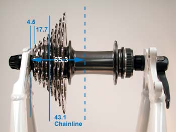
The rear cog middle is effectively 43.1 mm from the bike center line. The front chain rings should be about the same distance from the center line. It is possible, however, to still have acceptable shifting with less than perfect chainline. Manufacturers typically specify a front crankset chain of slightly longer than the rear chainline. In this case, as 45 mm chainline would likely work. A 50 mm chainline would probably be too long.
Shifting Issues Related to Chainline
If either the front or rear sprockets are either too much inward or outward relative to the other, there may be certain shifting problems. However, if a bike chainline measures off, yet the bike has no problems shifting, the bike should be considered acceptable. No “fixing” of the chainline is then required. The following are typical problems that may be caused by chainline issues.
- Chain jumping off large chainring when front derailleur is correctly adjusted.
- Chain riding off lower derailleur pulley when derailleur or hanger is not bent
- Chain rattling on inner faces of front chainrings.
- Chain derailling off inner chainring when front derailleur correctly adjusted.
- Front derailleur cannot be adjusted to stop over shifts while still allowing good shifting.
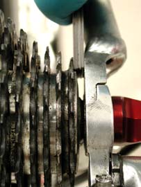
On certain bikes, the chain may tend rub and rattle against the front rings while riding in certain gear combinations. This is common on many bike when riding in the so-called “cross-chaining” combination of the smallest front ring, and the smallest rear cog. An example of a gear combination that is likely to rub is shown below.
Generally, the shorter distance from the bottom bracket to the rear hub, the more likely a rattle from gear combinations will occur. There may in fact be several gears that are unusable on any given bike. It is possible to minimize or eliminate this problem by moving either the front or rear cogs. Even if the bike has a so-called perfect chainline, it may help the riding and shifting to create an “error” to solve existing shifting issues.
Rear Cogs to Front Rings—Effective Chainline
Chain line gauges helps determine effective chainline of the front and rear gears. The tool references off the rear sprocket center and extends this line forward toward the front rings.
To use the (discontinued) CLG-2 chain line gauge, begin by checking the centering of rear wheel in frame. It should be centered between chain stays. Begin by getting the chain out of the way. Shift chain to smallest freewheel cog, and the innermost chainring (smallest ring). It is sometimes necessary to drop the chain off the front chainring onto the bottom bracket so it does not strike to CLG-2.
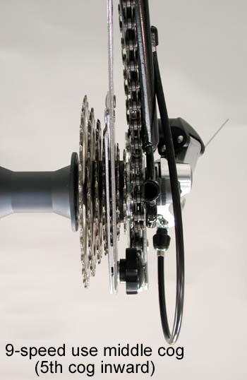
For odd numbered rear cogs (5-, 7-, 9-speeds), clamp the CLG-2 over middle cog. Snug the knob and do not over tighten.
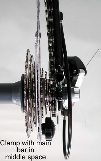
For even numbered rear cogs (6-, 8-, 10-speed), the middle of freewheel is a space, with the same number of cogs on either side. Clamp the CLG-2 so the main bar is falling in the middle space. The tool will clamp the cog inboard of this middle space (4th cog of 6 speeds, 5th cog of 8 speeds, 6th cog of 10 speeds.) Snug knob and do not over tighten.
Extend sliding gauge close to chainring, but do not allow contact with chainrings or the front derailleur. Most freewheels and freehubs have play. After clamping gauge, move CLG-2 end side to side, and hold end to center of play for most accurate reading.
Reading the CLG-2
Odd Numbered Cogs
Because the CLG-2 clamps over the center cog of odd-numbered freewheels (5, 7, 9), the black sliding gauge represents the middle of the rear cog set. The center of sliding gauge may or may not point to center of chainring set. If the sliding gauge is not pointing to the middle of the front crankset, estimate the amount to either side it is off.
NOTE: Most component manufacturers do not design drivetrains for “perfect” or center-to-center alignment. It is common for the chainrings to be slightly outward of the rear cog chainline by as much as several millimeters.
Even Numbered Cog Sets
For even numbered rear cog sets the CLG-2 clamps over the cog inboard of the cog set center. The main chrome arm, not the black sliding gauge represents the rear cog set center. It is therefore necessary to estimate the center where the end of the gauge points at the front chainrings.
For three ring cranks, the sliding gauge should point inboard, or just to the left from the rider’s point of view, of the middle ring.