Hub Overhaul and Adjustment: Cup and Cone Style
This article will discuss the adjustment and overhaul of "cup-and-cone" hubs. These hubs allow for access to internal bearings, and are adjustable. See related article for Freehub Service.
Hub Overhaul and Adjustment
Bicycle hubs may be either the adjustable cup-and-cone type or the non-adjustable cartridge style. The adjustable type bearing surfaces can be adjusted for bearing play. The cartridge types typically cannot be adjusted for wear or play. Both types can come in either the freehub type or the thread-on freewheel style.
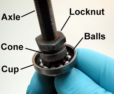
A basic bearing system is seen below. The cup is normally a permanent press fit into the hub shell. The cone traps the ball bearing. The locknut is tightened against the cone to prevent the cone from moving. If there is looseness from bearing play, the cone can be move closer to the cup.
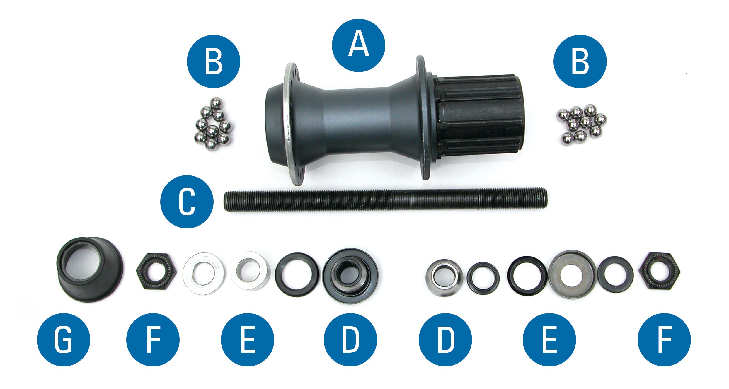
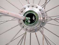
Modern freehubs tend to be more complex. The hub will have a freehub mechanism attached to the hub. The cassette cogs attach to the freehub. It is possible to remove and service the freehub in a separate operation. See Freehub Service. A typical rear hub with freehub is seen below.
Cartridge Bearing Hubs
Hubs using cartridge type bearings are not serviceable in the sense that they can be dismantled and adjusted. As cartridge bearings wear and develop play, the entire cartridge unit is replaced. Cartridge hub service is not covered in this article.
Common cartridge bearing type hub
Hub overhaul
- For rear hubs, begin by removing the cassette or freewheel. Remove quick-release skewer. If it is a solid axle type, remove axle nuts.
- Inspect axle ends. Measure and note the amount of axle protruding past locknut. For quick-release hubs, counting the number of threads is an adequate measurement.
- (OPTIONAL) Mount in axle vise, if possible. Mount right side down with left side facing upward. Generally, dismantle from the left side.
- Remove any rubber cover. Use a tie or string to hold small parts in the same orientation as they came off of hub.
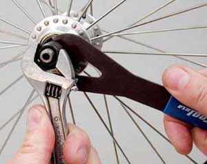
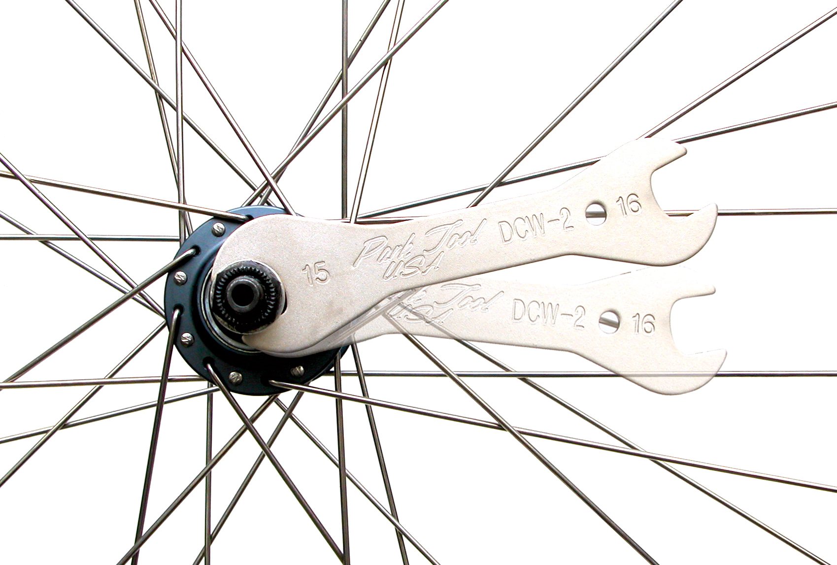
- Hold cone using cone wrench, and loosen locknut counter-clockwise.
- Remove locknut and any washers, placing them on the tie.
- Remove cone by turning counter-clockwise.
- Place hand below right side, and lift wheel slowly. Be prepared to catch bearings that fall from hub. Place wheel on bench.
- If inspecting bent axle, remove right side locknut and cones. Note that left side and right side cones, washers and locknuts may be different. Do not confuse left and right side parts. Use tie method to keep track of parts. Also note axle thread may be asymmetrical. The side with more axle spacers gets more axle thread.
- Count the number of bearings on each side, and then use pencil magnet to remove bearings from hub shell.
- For many hub models, it is possible and recommended to overhaul with the pressed dust caps in place. Dust caps may be fragile and removal may result in damage. Work around dust caps when cleaning and inspecting.
- Wipe and clean all parts. Parts must be dry for assembly. Wipe freehub mechanism out using damp rag. Do not soak freehub in solvent. Freehub bodies are lubricated internally with a light lubricant, and soaking them with solvent will remove lubrication. For freehub service, see Freehub Service.
Hub and Parts Inspection
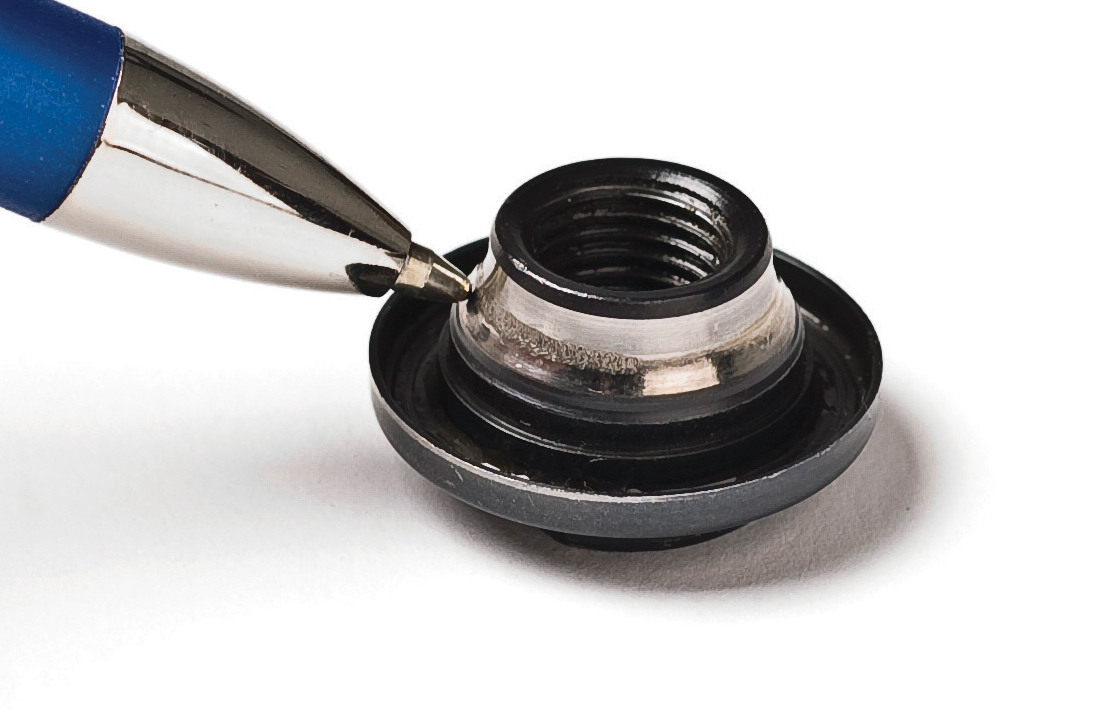
View hub cups and cones for pitting or damage. Also use a ballpoint pen to trace the bearing path. Roughness and wear will be felt as the small ball of the pen passes over pits.
Inspect ball bearings for shininess and brightness. If balls are dull looking, they should be replaced. If the cup is damaged, it typically cannot be replaced. A new hub would be required. Cones are typically available as replacement parts.
If inspecting axle, roll axle on flat surface. View axle close to surface and watch for gap appearing as axle rolls. Bent axles cannot be re-bent. A new axle is required.
Hub Assembly
- Grease axle threads.
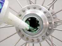
- Grease heavily inside hub shell cups.
- Place ball bearings in both cups and cover with more grease. Make sure balls are seated flat in cup. For rear hubs, the common number is 9 balls of 1/4-inch diameter per side. For front hubs, the common number is 10 balls of 3/16-inch diameter per side.
- If all parts were removed from axle, install right side parts. Use care to install in the same orientation as they came off. Return axle protrusion to the original measurement, as noted earlier. Tighten cone locknut fully.
- Install axle through right side of hub.
- Install left side axle parts, using care to install in the same orientation as they came off. Do not set axle protrusion on this side and do not tighten locknut at this time.
- For quick-release type hubs, snug the cone down until it contacts the ball bearings, and turn back counter-clockwise one quarter turn (90 degrees). This will purposely make the bearing adjustment too loose. Hold cone with cone wrench and tighten locknut fully. Proceed to HUB ADJUSTMENT below.
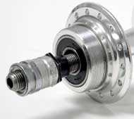
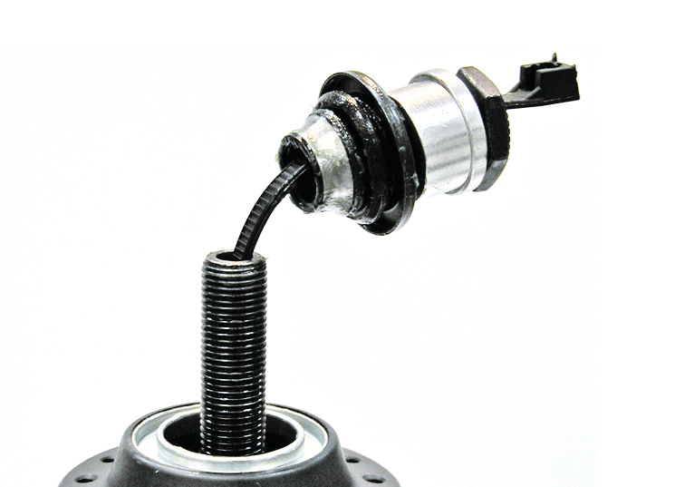
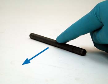
NOTE: For quick-release wheels, it is critical the axle end sit inboard or recessed inside the frame or fork dropout. This allows the quick-release skewer to secure onto the frame or fork end. If the axle end protrudes even a very small amount, the wheel may not properly secure and may come out during use. In the image below the axle end is only slightly too long. If the hub is the correct width, check the axle is centered between the locknuts. It may be necessary to grind off the axle end until it is safely recessed. See image below.
Hub Adjustment of Cup and Cone
Quick-release hubs have hollow axles that flex slightly when the quick-release is closed. Hub bearing adjustments must account for this extra pressure. When a quick-release hub is not clamped tight in the frame, there should be a slight amount of play in the axle. This play disappears when the hub and wheel are clamped in the frame.
To test the bearing adjustment of a bike, grab the wheel while it is still in the frame and pull it side to side. Turn wheel and test again, feeling for a knocking sensation. If no play is felt, remove the wheel. Grab the axle (not the skewer) and rock it up and down to check for play. If the axle has play when the wheel is outside the bike, but no play inside the bike, the adjustment is adequate. If there is no play in the axle when the wheel is outside the bike, the adjustment is too tight, even if the axle seems to turn smoothly when out of the bike.
Bearing Adjustment Procedure
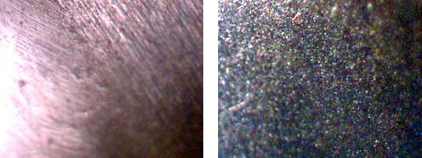
It is difficult to adjust bearing by using a subjective feeling of smoothness. Generally, adjust bearings for the loosest setting that has no knocking or play, regardless of this relative smoothness. Due to the inherently non-perfect surfaces of the races and ball bearing there will always be some amount of “drag” or roughness. See image below.
Bearing adjustment is done by moving the threaded cone races closer or away from the cup races. Locknuts then lock against the cone to hold it in place. Proper bearing adjustment is a precise and sometimes time-consuming job. Several attempts at adjustment should be expected before an acceptable adjustment is found.
The goal for adjustable bearings is to have the bearings rotate as freely as possible without any knocking or play. When beginning a bearing adjustment, start with it loose and then proceed to tighten the adjustment in small increments until the play disappears. This ensures the adjustment is as loose as possible but is without play. In most cases, try to make small changes, in increments of 1⁄32 of a complete rotation. Assuming you have the common 32-hole rim, imagine rotating a cone wrench only the angle of spoke to spoke while making adjustments.
The bearing adjustment should be done only on one side. For a rear wheel, the bearings are adjusted on the left side. Remove any rotor as necessary to get at the cone.
For a front wheel assume adjustment is done on the right side. If it is a front rotor hub with a disk, the right side is more accessible. As a habit, adjust the right side of a front wheel.
When possible, hold the non-adjusting side in the soft jaws of a vise. It is possible to adjust without a vise, but expect the axle to turn and change your adjustment. This will slow the process.
- Hold the adjusting side cone with a cone wrench. Note the orientation of the cone wrench as a reference when changing the adjustment.
- Use another wrench to loosen the locknut.
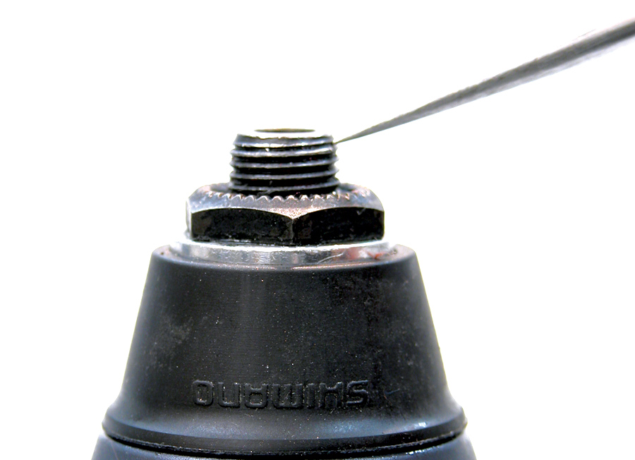
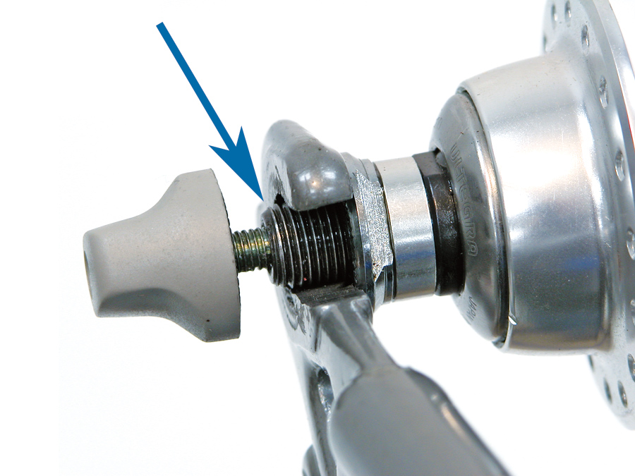
- To tighten the bearing adjustment, turn the cone clockwise a small amount such as 1/32 of a turn (see figure below).
- Hold the cone from moving and secure the locknut fully.
- Check the hub for bearing play.
- When there is a slightly amount of play in the hub, test the adjustment by mounting the wheel in the frame or fork.
- Fully tighten the skewer and check the bearings for play by pulling side to side on the rim
- If there was a slight amount of play with wheel outside the frame, but no play when wheel is secure in bike, the adjustment is considered adequate. Install sprockets and other parts.
- If there is still play after mounting wheel with skewer closed, the bearing adjustment is too loose. Remove the wheel and proceed to further tighten the cone from step 1 here.
NOTE: If a bearing adjustment cannot be found that has no play and yet turn reasonably smoothy, it is likely the internal bearing surfaces are worn out. If play does not disappear until bearing adjustment is very tight, right side locknut may not be tight against cone, or cups inside hub shell may be loose.
Hub Adjustment - Solid Axle
If the wheel uses a “solid axle”, with no quick release hub system, the adjustment outside the bike is considered the same as when the wheel is mounted in the bike. There is no need to allow for axle flex as with quick release hollo axles. Adjust the bearings until you find the loosest adjustment that has no play.