Crank Removal and Installation: Self-Extracting
This article will review removal and installation of self-extracting type cranks.
Getting Started
- Pin Spanner (for some retaining caps):
- Hex Wrenches for crank bolt and some retaining caps
- Hammer: HMR-4
- Torque Wrench
- Thread Preparation:
- Rags
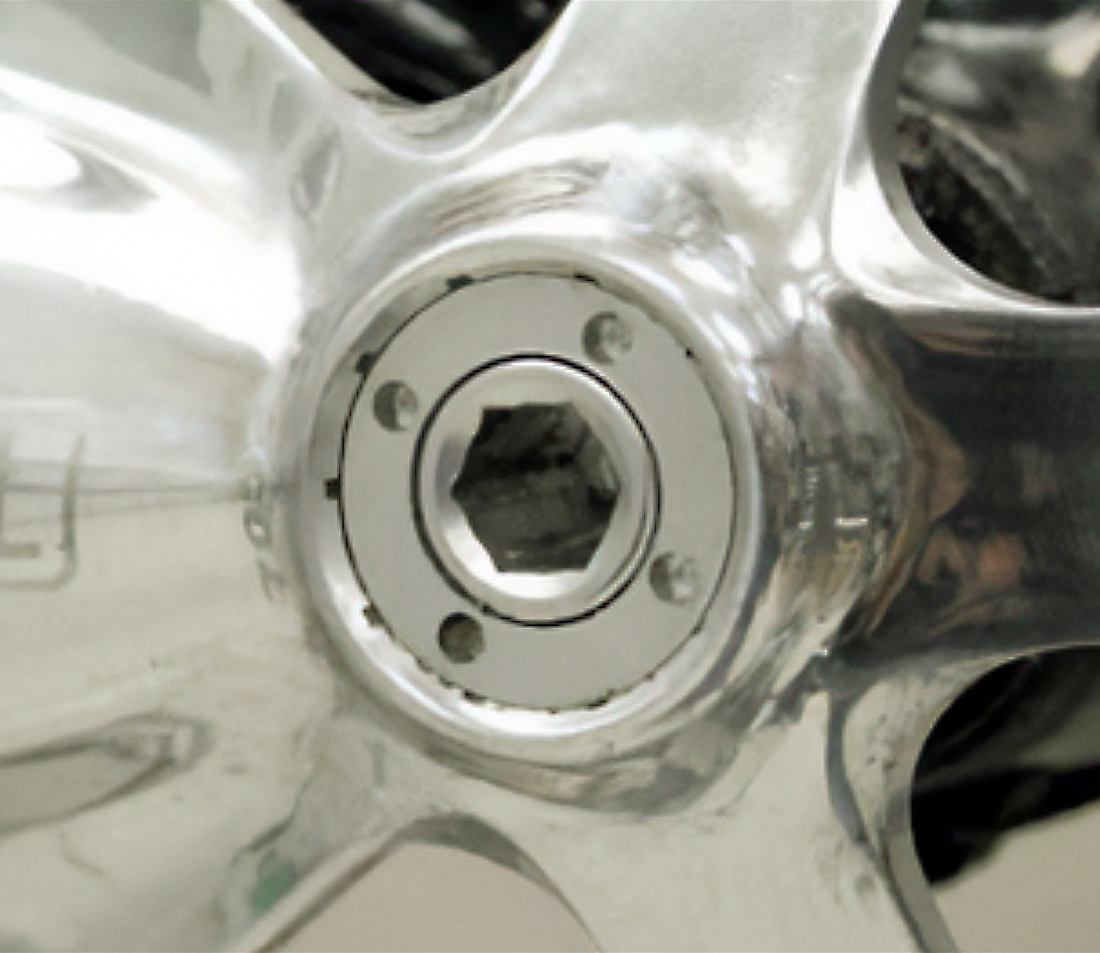
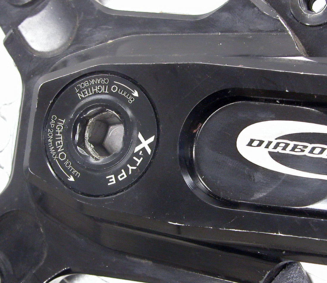
Self-extracting system with pin holes in retaining cap
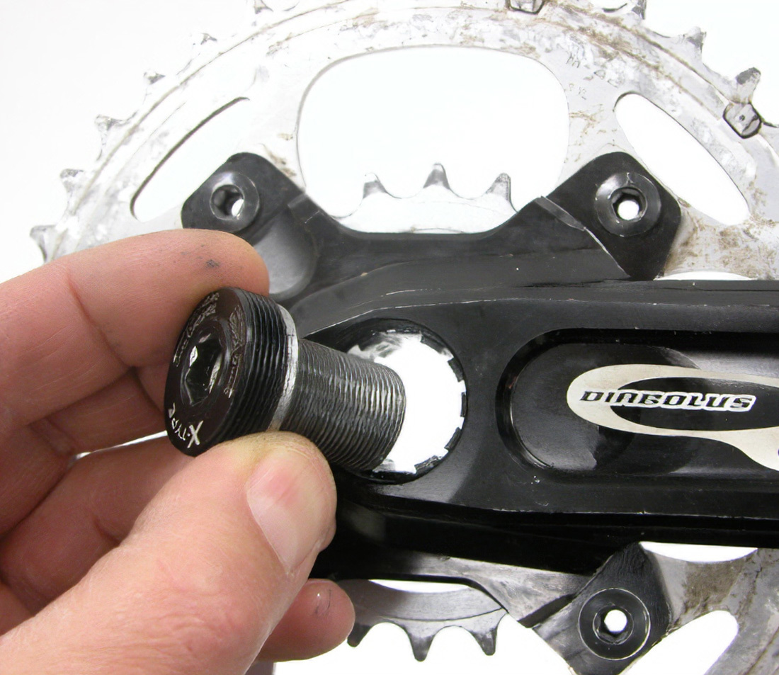
Self-extracting system with hole fitting in retaining cap
Many manufacturers offer both two-piece and three-piece cranksets with a “self-extracting” or “one-key release” system. The crank puller is effectively built into the crank. Self-extracting systems use threaded rings that look similar to a crank dust cap. However, these crank retaining rings are threaded over the crank bolt, so that when the crank bolt is loosened the shoulder of the bolt presses back against the ring, which in turn slowly pushes the arm from the spindle. No additional crank removal tools are required.
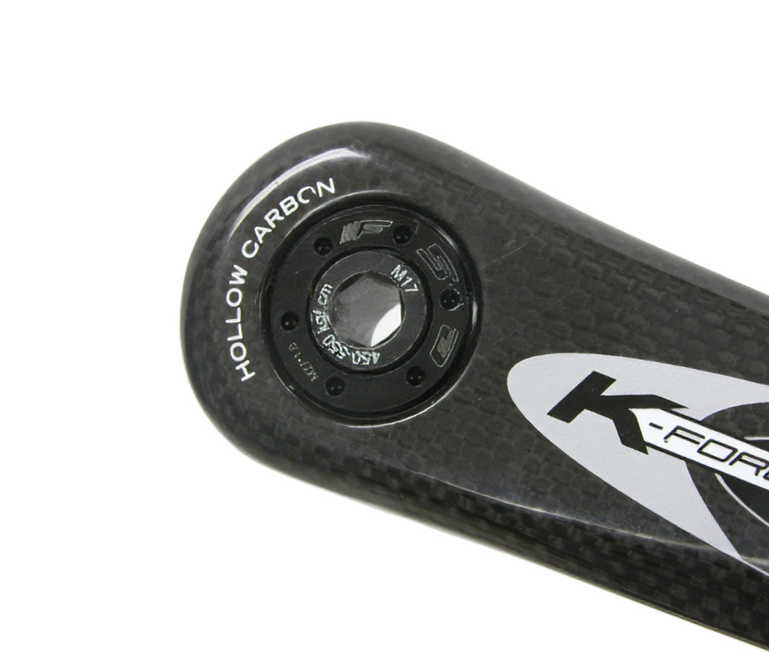
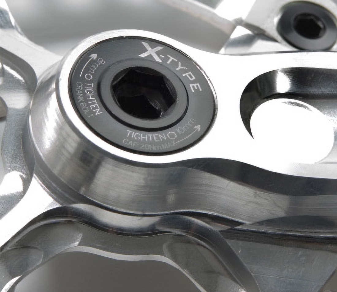
FSA® self-extracting arm with ring and bolt in place
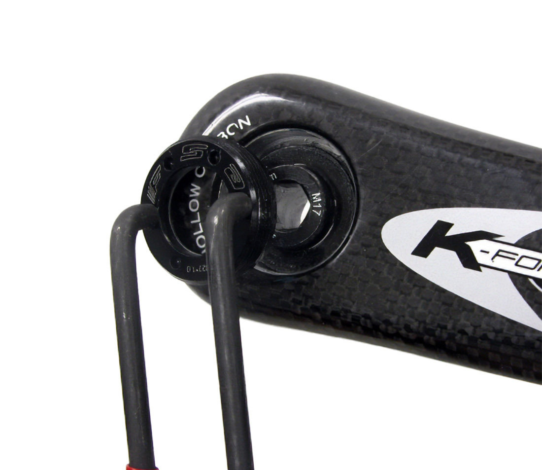
FSA® retaining ring removed with SPA-2. Bolt is below ring.
The crank bolt of the self-extracting system is right-hand threaded (tightens clockwise and loosens counter-clockwise). The retaining rings can be either left- or right-hand threaded depending on the manufacturer, and are often indicated by arrows on the cap. Rings are secured using pin spanners or hex wrenches. Some SRAM® and Truvativ® rings may use a 16mm hex wrench to secure. If you don’t have a 16mm hex wrench, you can use a fractional bolt with a 5/8″ hex head and cone wrench as shown.
Self-extracting systems require extra care when installing the crank to the spindle. The self-extracting system makes it difficult to see how the arm is fitting onto the splines of the spindle. Cranks and spindles must align and mate properly as the crank is pressed onto the spindle. A forced mismatch can damage the crank. Splined cranks without the self-extracting cap system allow easy viewing of the crank to spline fit. If there is concern about mating the spindle to the arm, remove the self-extracting cap, install the crank, and reinstall the retaining ring.
Crank Removal
Race Face® self-extracting and retaining ring. Notice arrow to tighten ring counter-clockwise
Race Face® retaining ring and bolt removed
- Leave the retaining ring of the self-extracting systems in place in the arm. Do not remove the retaining ring. Check that the retaining ring is secured into the arm before starting removal.
- Begin unthreading the crank bolt using a hex wrench. Continue loosening until the crank arm slides off the spindle.
- Remove remaining the crank arm. Take note of the location and orientation of any washers and spacers as you are removing.
- Two-piece: Remove the remaining crank arm by pulling it away from the bike and out of the bottom bracket shell. It may be necessary to gently tap the spindle using a mallet.
- Three-piece: Repeat steps 1 and 2 on the right side crank arm to remove from the bottom bracket spindle.
Crank Installation
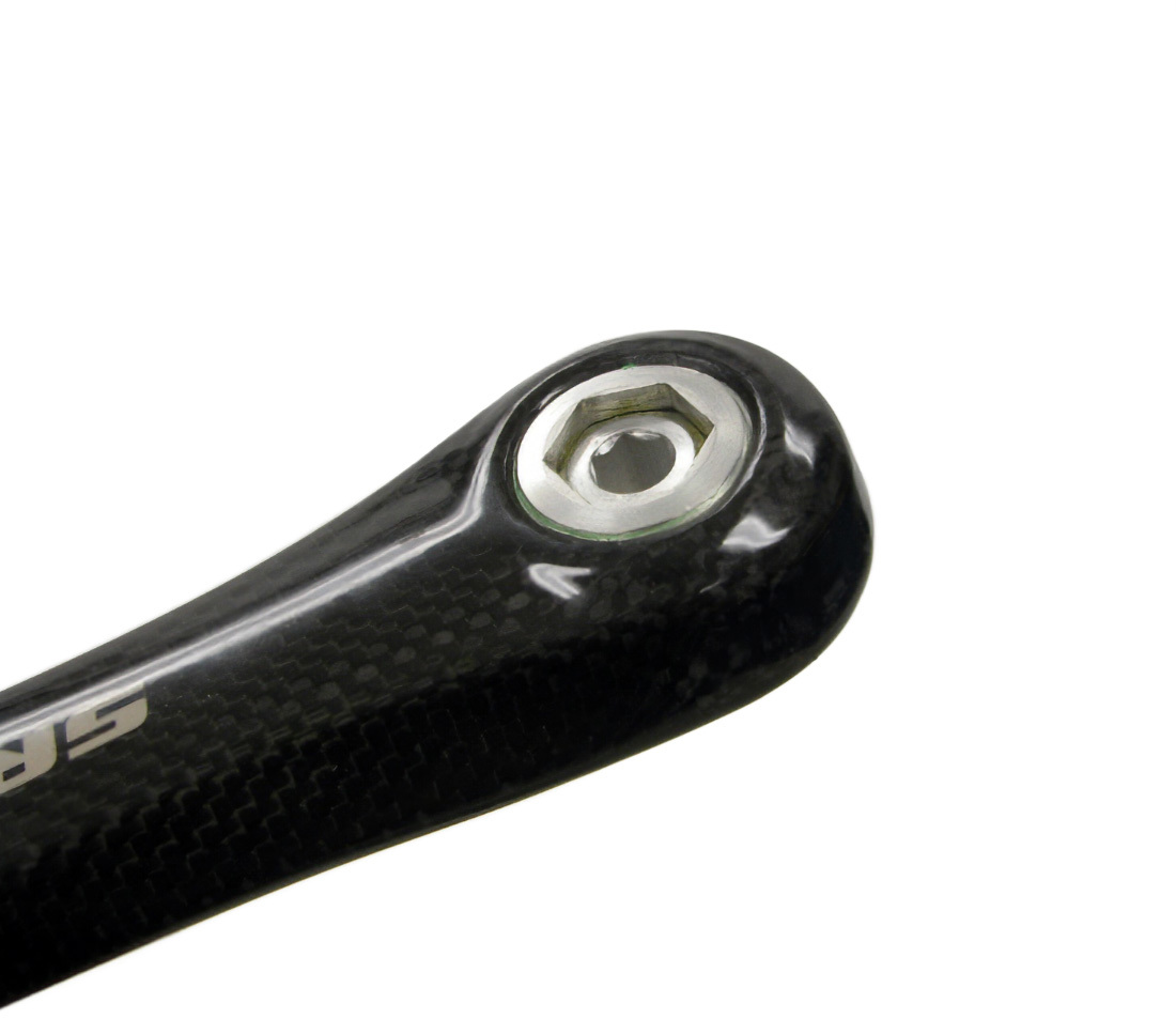
SRAM® and Truativ® use a hex shaped in self-extracting retaining ring
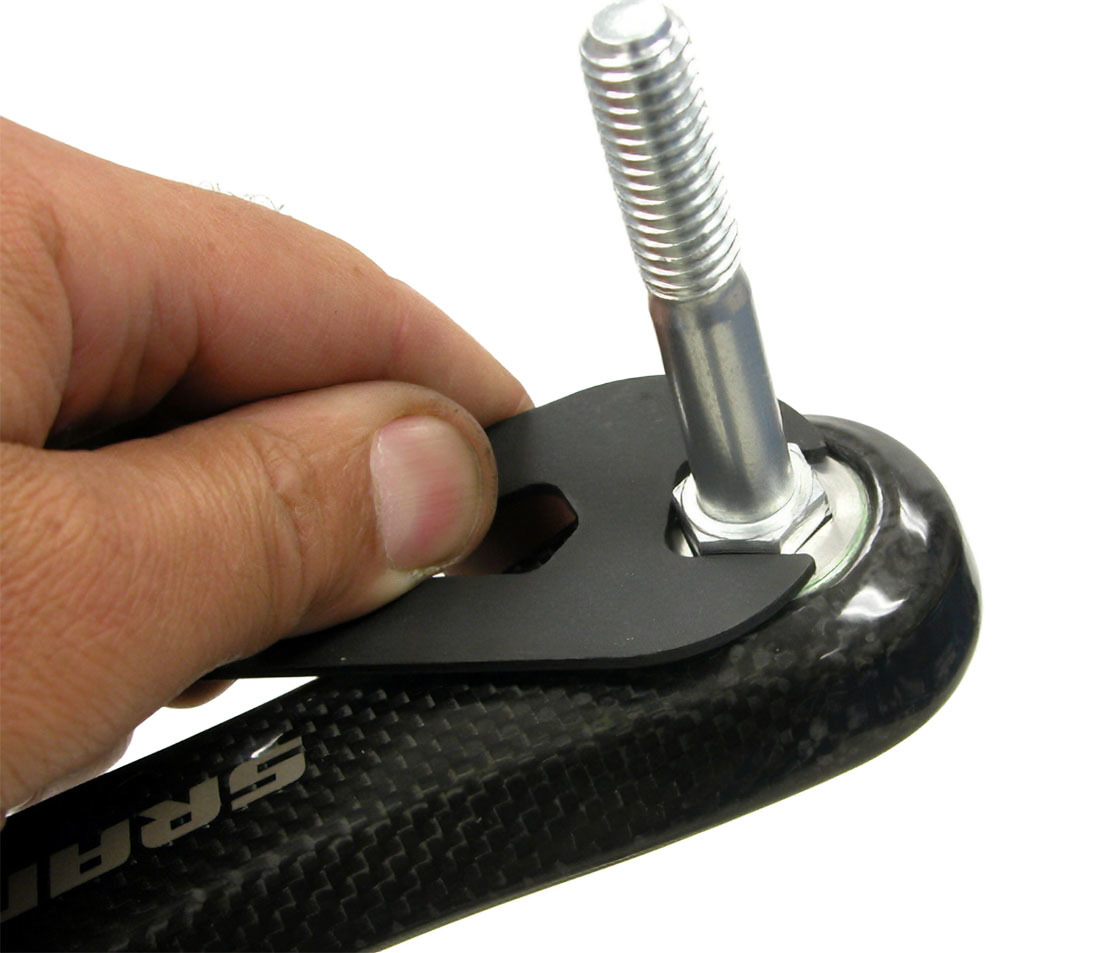
SRAM® retaining ring uses a 16mm hex to secure. Use a 5/8" hex head bolt as a substitute.
- Grease spindle surface and internal crank bolt threads. Reinstall first crank arm, positioning any washers or spacers as needed:
- Two-piece: Insert crank arm with integrated spindle through bottom bracket shell. The fit can be snug, and in some cases gentle use of a mallet may help.
- Three-piece: With crank pointing straight down to the six o’clock position, rotate spindle so it appropriately matches with the crank fitting. Using a hex wrench, begin carefully threading the crank bolt into the spindle as you maintain alignment. Secure crank bolt fully to manufacturer’s specifications.
- Reinstall remaining crank arm 180° from the first, ensuring that the crank-spindle interface mates correctly. Using a hex wrench, begin carefully threading the crank bolt into the spindle as you maintain alignment. Secure crank bolt fully to manufacturer’s specifications.
- Check retaining rings for tightness.
Related articles
Three-Piece Crank Removal and Installation View Article
Crank Removal and Installation: Two-Piece Compression Slotted View Article