Pedal Retention Systems and Cleats
This article will discuss the various foot retention options for the bicycle. The pedals of the bicycle accept the foot and shoe. The cyclist's shoe is really the beginning of the bicycle drive train, especially if the intention is to achieve high performance. A sloppy fitting shoe will be as inefficient as loose bearings.
Getting Started
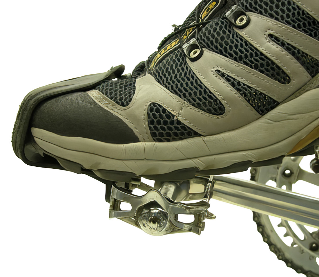
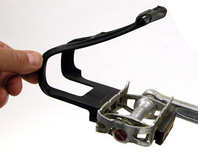
Pedal retention systems are useful to help riding efficiency. Without a retention system, the feet can inadvertently flying off the pedal (Figure 1). However, a common cycling myth is that toe clips and clipless pedals allow the rider to “pull on the backstroke” and hence apply force around the complete pedal stroke. There is always a part of the pedal cycle that is the “power” stroke, and part that is “dead”. Pedals do add help by keeping the foot secure during the power stoke. Riding with any foot retention device will require some skill development.
Toe Clips
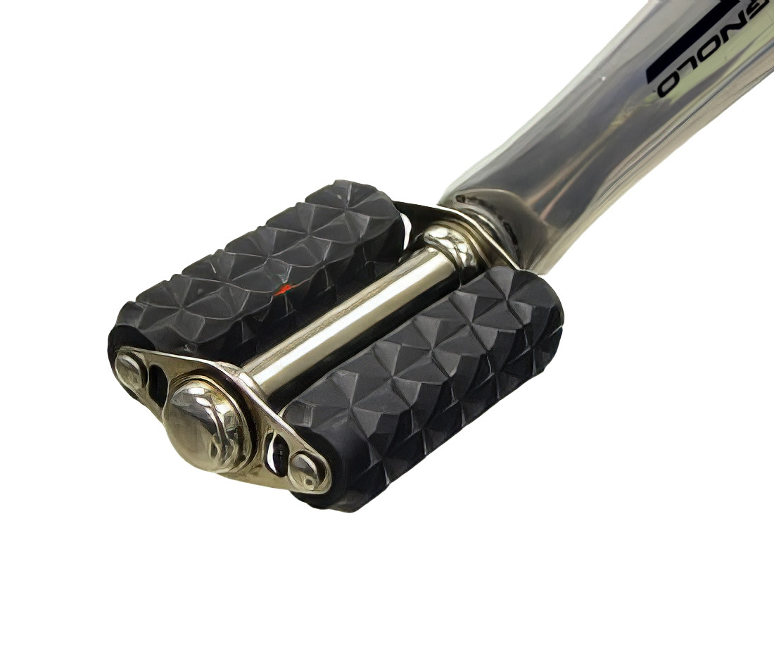
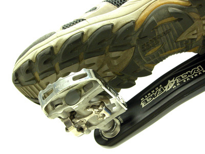
The toe clip is a simple and traditional method to help secure the feet. These are attached to most platform or “quill” pedals. A simple version is the “mini” toe clip that has minimal overlap of the shoe (Figure 2). There is no strap. The foot can exit to the side or to the back. It does help retain the foot, but is not a secure as other systems. It can be used with most recreation running type shoes.
The next level up in feet security is the full toe clip with strap (Figure 3). These can also be used without strap, and will add more security then the mini clip. Adding the straps adds significantly to the security. The position of the foot over pedal can be adjusted with toe clips of different lengths, such as short, medium and long. It is also possible to add some spacers between the pedal and clip to gain some additional length. Toe clips may come in either steel or plastic.
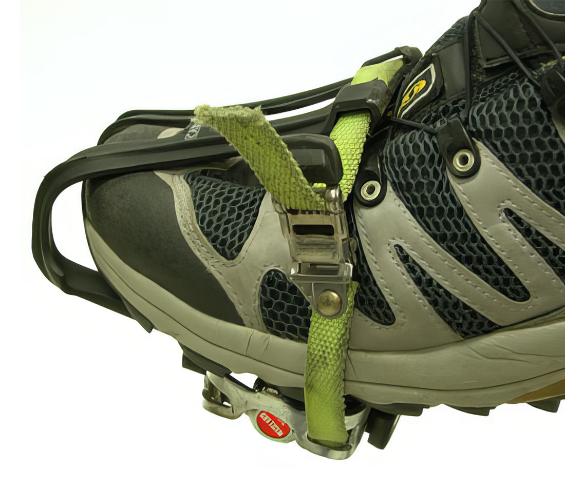
The toe strap fits through the pedal and around the foot. The end of the strap then passes under a roller and through the buckle, and is engaged by the buckle teeth (Figure 4).
There are also pedals that have two different sides. One side is a clipless pedal fitting, while the opposite side is a platform that requires no cleated shoe (Figure 5).
Clipless Systems: Road Racing
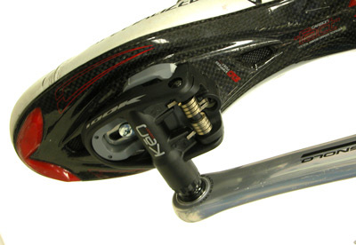
The clipless pedal systems of performance road pedals require a cleat or special fitting designed into the sole of the shoe (Figure 6). The cleat will engage with the pedal. Brands vary in design and typically do not interchange.
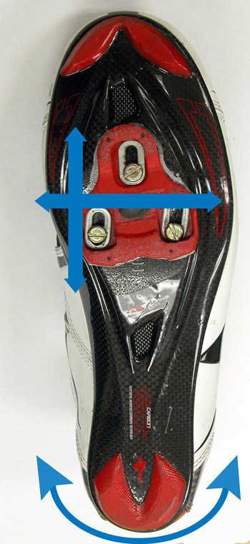
Cleats will eventually wear out with use. If you are comfortable in the current cleat position, use a marker and delineate the outline (Figure 7). The new cleat will then be placed to match the outline and secured.
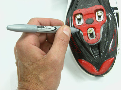
The cleat may be moved under the sole of the shoe forward, backward, rotated, and slid left-to-right (Figure 7). The idea is to set the cleat position so is comfortable while cycling. Generally, the position of the foot should simulate the natural gait when walking.
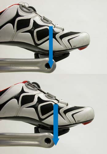
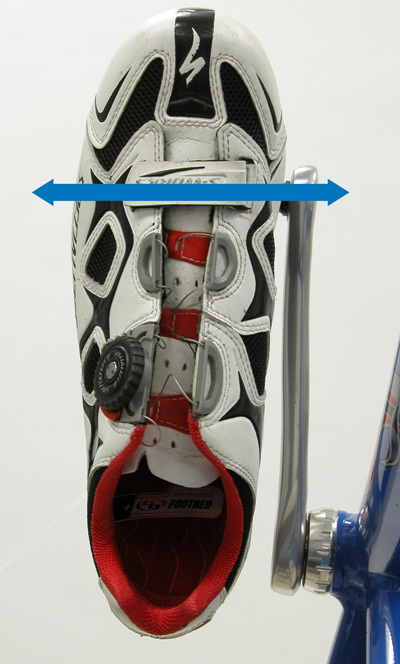
The fore-to-aft of the cleat moves the foot relative to the pedal spindle. The blue arrow shows the position of the joint of the first metatarsal, the joint of the big toe. This is a useful as a reference point when setting cleat position. The top image in Figure 8 shows the foot set close to the pedal spindle. This type of position would be used by a rider that generally prefers a higher cadence using relatively lower gears. They are said to be “pedaling on their toes.” The lower image has the cleat slid back on the sole, which places more of the foot forward relative to the pedal spindle. This would be used by someone who preferred a relatively slower cadence, possibly pushing a larger gear ratio.
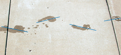
The cleats allow the shoe and foot to rotate clockwise or counter-clockwise to some degree. This is a very important angle for rider comfort, performance and health. If the foot position is off, it will stress the joint connections of the knee, hip and or ankle. The concept can be seen when wet feet leave a print on cement (Figure 9). The rotation of the cleat should simulate this angle.
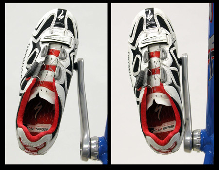
In Figure 10, the left image shows the extreme rotation of the cleat. The foot is pointing inward, or “pigeon toed.” The right image is the extreme inward motion of the cleat, or more “duck footed.” Notice in this example the shoe is actually striking the crank, making this particular setting impossible to use.
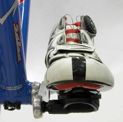
The cleats can also be moved inward or outward, independently of rotation. This is also known as medial and lateral adjustments. If a person is satisfied with the rotation of the cleat, but the heal of the foot strikes the crank, the shoe should be move laterally outward, not rotated outward (Figure 11).
Pedals are designed to be level or flat (Figure 12). The human foot, however, may or may not work well in this position. There is typically no cleat adjustment for this, and the shoe must be fitted with an insole.
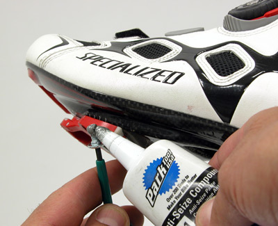
It is recommend the threads be treated for either road or off-road cleats (Figure 13). Options include thread lockers, grease, and anti-seize compounds such as Park Tool ASC-1. The anti-seize compound will resist water, mud and dirt to a much greater degree then grease.
Clipless Systems: Off-Road
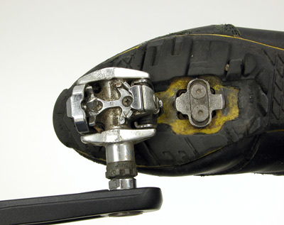
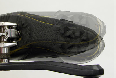
Clipless systems for mountain bikes and for clipless touring shoes are similar to road racing shoes. A cleat recessed in the sole is designed to engage the pedal (Figure 14). The shoe sole tends to be softer rubber and flex for walking.
Some clipless systems (both road and off-road) may be designed to “float” (Figure 16). The concept behind float is that the joints of the leg are then not locked. Cleat alignment is then, in theory, not as critical. However, excessive float can make the handling of the bike less the precise.
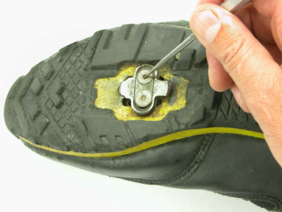
Off-road cleats, even though recessed, will wear out and require replacement. The cleat bolts are often filled with mud and detritus. Clean the screw head to ensure full engagement of the hex wrench. Use a seal pick or a ground spoke as necessary (Figure 17).
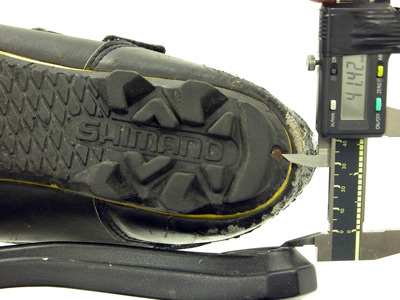
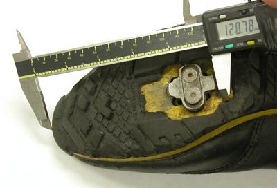
It can be difficult to outline the cleats as described for changing road cleats. However, it is possible to record the current cleat position by measuring it placement relative to the shoe. Measure the fore-aft from the front of the shoe to a fixed point on the cleat (Figure 18).
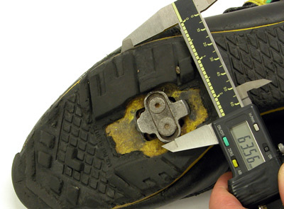
Measure the lateral adjustment from the side of the shoe to a fixed point on the cleat (Lateral 19).
To measure the rotation adjustment of the cleat, engage the shoe in the pedal. Push the shoe close to the crank and measure from the crank face to a fixed point on the shoe (Figure 20). Use these numbers to duplicate setting with new cleats.