Written by Calvin on February 28, 2009/Calvin's Corner
Gore® Ride-On® Cable Installation
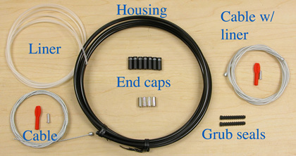 Figure 1. The Gore® Ride-On® cable system
This article will describe the installation of the Gore® Ride-On® cable system. This is a cable housing system that relies on a tubing system to seal the inner shifting or brake wire, thereby preventing dirt and water from entering. The system is composed of housing, a full length removable liner tube, a coated brake (or shift) wire, end caps (ferrules) for both frame housing stops and component housing stops, “grub” seals for ends of the wire system, cable end crimps, and crimp covers (Figure 1).
Begin by removing the old cable and housing from bike. You may want to use the old housing to determine the length of the new housing. However, do not assume old housing was cut to an acceptable length. Housing should approach housing stops in a straight line. Excess housing will mean more cable drag. Short housing will bind the cable at both ends. Hold the housing in place and view the housing as it approaches stops at the brake or the derailleur (Figure 2 and Figure 3).
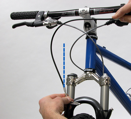
Figure 2. Housing length that is too long
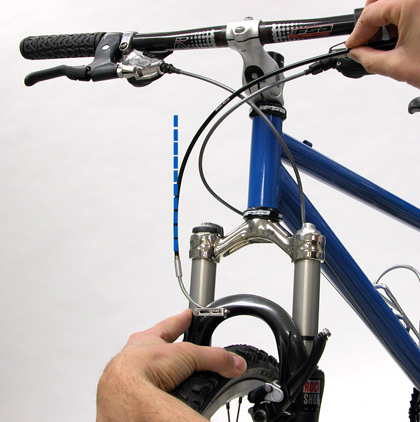
Figure 3. Acceptable housing length entering stop in a straight line
Both shift and brake Ride-On® cables are double-ended. The brake cables have a drop bar lever on one end and a barrel end for flat bar levers on the other. Cut off the end not required (Figure 4). Shift levers have barrel fittings on both ends. One is slightly larger at 4.4mm for Shimano and SRAM. The smaller barrel is 4mm for Campagnolo systems.
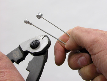
Figure 4. Use the CN-10 to cut off end not used
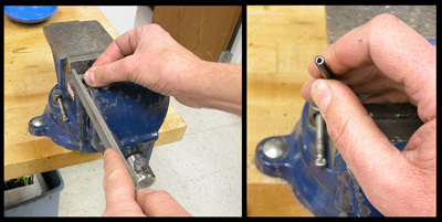
Figure 5. Finish brake housing end
Finish the cut housing end with a file to eliminate any burr or sharp end. Use a cable cutter to minimize fraying of the wire end, and file the housing end square if necessary (Figure 5). Compressionless shift housing is simply cut squarely with cable cutters such as the CN-10; filing to finish compressionless housing ends is unnecessary.
Draw out the inner wire from the liner. Install the wire into the lever (shift or brake). Install the liner into the housing. The liner has one end that is flared. This end will face the either the shift or brake lever. Use a silver colored end cap when these fit into lever housing stops (Figure 6). If end caps do not fit into the stop, the stop is sized acceptably for housing alone.
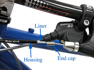
Figure 6
Figure 7. Remove short liner from "noodle" of linear pull brake
For linear pull brakes, remove any short liner already installed in the housing “noodle” for the brake (Figure 7). The liner from the Ride-On® set will provide the liner for the noodle.
Pull the housing and liner fully into place. The liner tubing should extend past the stop by approximately 10mm or 3/8-inch. Use a marker and mark where liner will be cut (Figure 8).
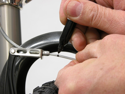
Figure 8. Mark liner for trimming
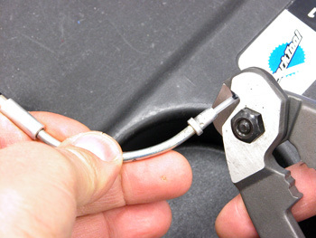
Figure 9. Cut liner tubing without shift/brake wire in place
Remove the cable from liner tubing and cut the housing at the mark. This avoids any damage to the coating on the brake/shift wire (Figure 9).
Reinstall wire through the tubing and though the component housing stop, either at the brake or derailleur as appropriate. Install the grub seal. This rubber boot will help seal the system. The larger end of the seal should slip over the liner (Figure 10).
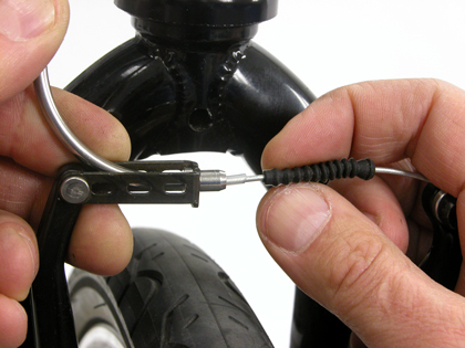
Figure 10. Install grub seal over liner end
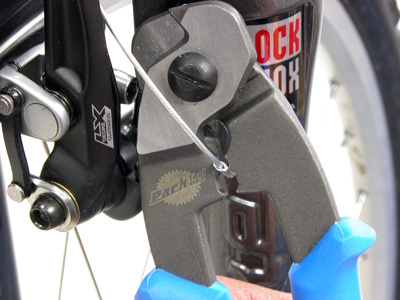
Figure 11. Crimp cable end using crimper section of CN-10
Pull cable slack from the system and secure the cable pinch bolt. Cut off excess cable and install the end cap, cinching it with the crimping section of the Park Tool CN-10 (Figure 11).
The arrangement of the cable, liner and housing is the same as the brake lever (Figure 12).
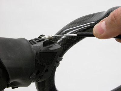
Figure 12. Shift housing arranged at an integrated brake/shift lever on a drop bar
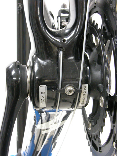
Figure 13. Liner running under bottom bracket and through frame
The liner must run the length of the frame for the rear brake and both derailleurs. Work with care to avoid kinking or damaging the outer tubing (Figure 13).
For front derailleur housing, cut the liner approximately 25mm (1-inch) below pinch bolt (Figure 14). Mark the liner at the appropriate point to cut. Remove inner wire, drawing it back at a minimum just beyond the point of cutting, and trim the liner length.
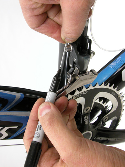
Figure 14. Mark housing for cutting and then pull wire past cut mark
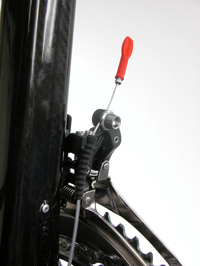
Figure 15. Components should not press on cable liner
Install the grub seal over the liner. Pull cable to remove slack and secure cable pinch bolt. It is important the linkage of the derailleur (or brake) not hit or press into liner (Figure 15 and 16). Install the end cap and the optional cap cover.
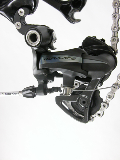
Figure 16. Grub seal will compress but should not interfere with derailleur linkage
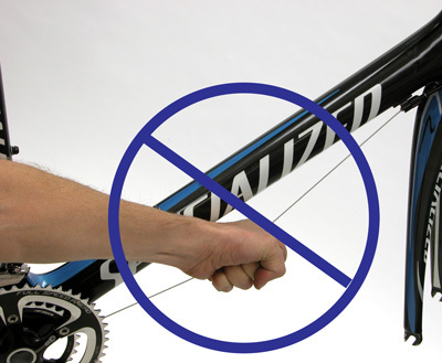
Figure 17. Do not pull directly on the cable and liner
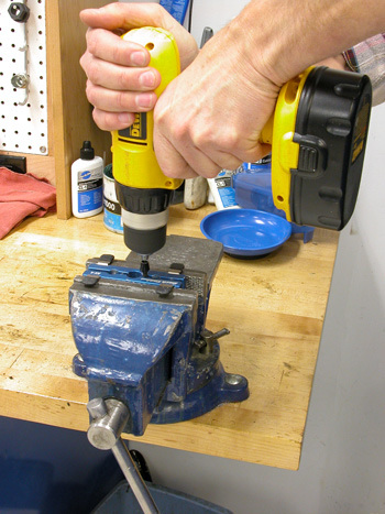 Figure 18. Drill housing stops only as necessary
It is important the liner not be pulled or stressed. Never grab the liner with cable and pull to set housing or to shift derailleur (Figure 17).
In some cases, it may be necessary to drill housing stops to permit the liner to pass. Use a 3/32″ drill bit (2.38mm) for this purpose (Figure 18). NOTE: Always consult the component and or frame manufacturer before drilling.