Di2 Shimano® Electronic Intelligent System Installation
This article will discuss the installation and adjustment of the Di2 Shimano Electronic Intelligent System®. This system is incorporated in the designs of some new bike models. This article will focus on the installation of the system as an after-market component system.
Getting Started
- Hex Wrenches
- Screwdrivers
- Shimano TL-EW01 tool
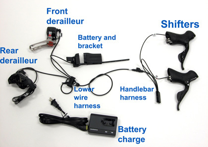
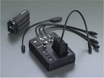
This system is incorporated in the designs of some new bike models. This article will focus on the installation of the system as an after-market component system (Figure 1). Both front and rear derailleurs of this system contain a solenoid to drive the shift, powered by a battery. Proper installation is important to this system. The mechanic should make it a point to read the manufacturer’s instructions. Do not assume old habits and techniques will work with this system.
Installation Of Parts
Much of the system installs as the Dura-Ace mechanical group. The rear derailleur mounts to the hanger as it always has. Use care, however not to push the cage back and forth by hand through its gear range swing. Forcing the cage outwards will damage internal gearing inside the derailleur body.
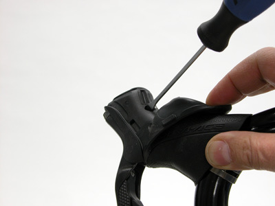
The shift/brake levers mount and secure to the handlebars as do mechanical STI shifters. The brake levers have a reach adjustment. Pull the top part of the rubber hood back to expose the reach adjustment screw (Figure 2). Tighten this screw to bring the lever back toward the bar for smaller hands.
The front derailleur is available in a band-type and a braze-on mount type. The band-type model is designed for use on a round seat tube and simply rotates as necessary to allow for correct alignment.
The braze-on model uses a rotation angle screw, or “support bolt”, which sets the angle of the derailleur cage to the chainrings by pushing against the frame and tilting the derailleur. The braze-on models include an adhesive pad to protect the frame from the rotation angle screw (Figure 3).
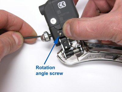
Figure 3. The "support bolt" will push against the frame to rotate the cage angle
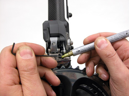
Figure 4. Mark a hex wrench to find the location of the rotation angle screw
It is important to set the protective pad correctly on the frame. This prevents the braze-on model derailleurs from drilling the setscrew into the frame. It can be difficult to set the protective pad height, and the setscrew must correctly contact this pad. To determine the pad location, mount the braze-on type derailleur on the frame and set it close to its final height. Snug the mounting bolt and remove the rotation angle screw (support screw) completely. Use a colored paint pen to put a spot of paint on the end of a hex wrench (Figure 4).
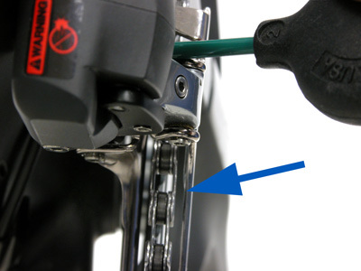
Guide the wrench into the hole of the setscrew and make a mark on the frame. This mark indicates where the protector pad should be placed (Figure 5). The protector pad adheres to the frame. Install the front derailleur and reinstall the setscrew. Check the alignment of screw and protector pad and reposition the pad as necessary (Figure 6).
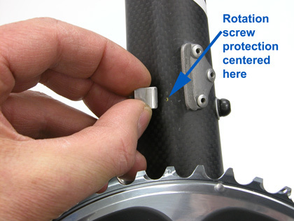
Figure 5. Gold paint mark from hex wrench marks placement of protection pad
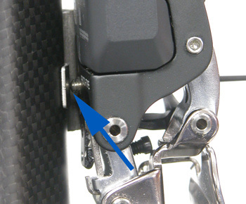
Figure 6. Setscrew correctly striking protective pad
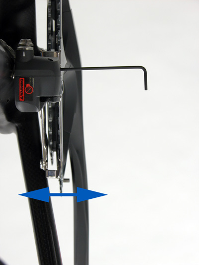
Install and set derailleur height: The front derailleur cage can be safely pulled to the outside to assist setting its height over largest ring. Set the clearance to approximately 2mm over largest chainring. To set the cage rotation, tighten the rotation angle screw, which flexes the body of the front derailleur. This moves the back end of the cage to the right, as seen from the rear of the bike. (Figure 7).
Electrical Wire Installation
Route and connect the wiring carefully care to avoid damage or wear to the electrical cable. Handlebars must be free to move left and right without binding the wires. However, excessive wire slack may lead to the wire being caught and pulled. Begin by installing the brake housing and securing the housing to handlebars with thin sections of tape.
The wiring system comes in two sections. The shift levers use the front wire harness (Labeled“Junction” by Shimano). A second harness comes from the bottom bracket to connect the battery and both derailleurs to the shift lever harness.
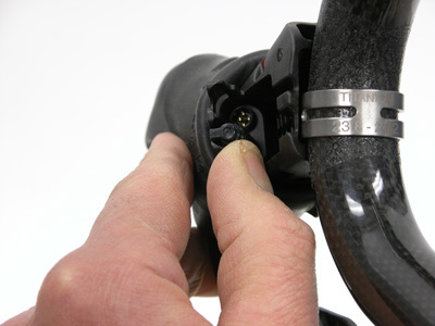
Attach the front wire harness to the shifters. The two wires ends are marked Left (For the front shifter) and Right (For the rear shifter). On the inner face of each lever is a plate or door that opens to expose the four-pin socket for the electrical wire fitting. Pull the rubber cover forward from the back to expose cover (Figure 8).
Shimano supplies a special tool (TL-EW01) to assist in installing the plug. Engage the plug into the tool, and then guide the tool into the lever (Figure 9). The plug has a guide stud that will align with the cover. Push the plug into place until you hear and feel a click. Remove the tool, leave the wire in place, and push the cover closed. Use tape to secure the shift wire to the handlebar (Figure 10). Repeat the installation on other side.
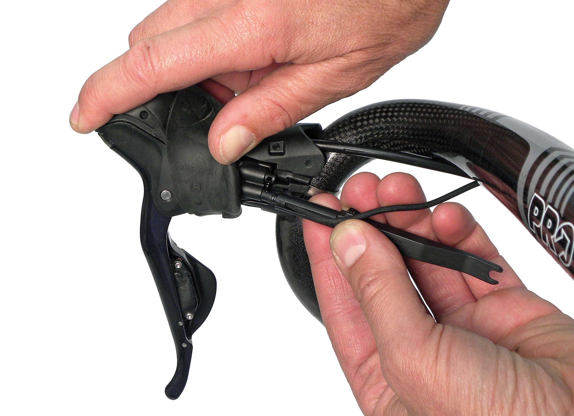
Figure 9. Shimano TL-EW01 tool pushing plug into socket receiver
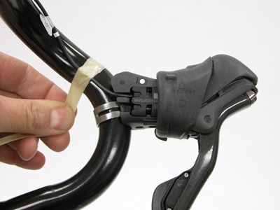
Figure 10. Secure electrical wire to minimize chance of damage
Consider the best routing options for the bike before securing the wire. Secure any loose wire with that may be caught with small zip-ties. Depending upon bar width, there may be excess wire length. If this length is left free and unsupported it may result in the wire getting caught and damaged (Figure 11). If excess length is available, it is best to wrap up the wire adjacent to the lever (Figure 12). If the bike were crashed, and the levers were to move, having slack available will help minimize stress on the wire.
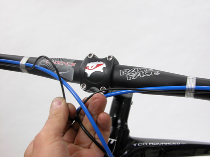
Figure 11. Excessive wire length may cause problems
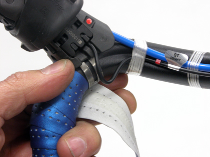
Figure 12. Wrap any excess wrap close to lever when possible
The front harness has a junction box that contains the shift mode switch (Figure 13). This switch may also be secured with zip ties to the front housing as appropriate.
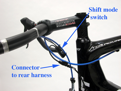
Figure 13. Front wiring harness
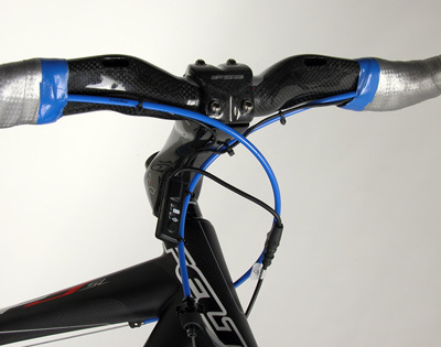
Figure 14. Secure excess wire to avoid it being caught or pulled
There is a connector at the end of the front harness that will plug into the lower harness. This connector may be secured to the rear brake housing. Secure any loose wire from flapping to minimize the possibility of damage (Figure 14).
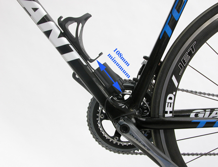
The shifting is powered by a battery, which is held by a bracket bolted between the cage and water bottle cage. There are several hole options in the bracket to ensure there is adequate room to install and remove the battery. Leave a minimum of 108mm between the cage end and the bracket end (Figure 15). However, do NOT install battery at this time.
The battery bracket connects to the lower wiring harness, which contains three wires: one wire for the front harness, one wire for the front derailleur, and one wire for the rear derailleur. The longest wire of this set connects to the front harness attached to the handlebars. The second longest wire secures to the rear derailleur and the shortest wire will connect to the front derailleur. All wires are marked. Shimano offers three different lower wire set length options.
The wire harness guide is installed in place of the bike’s mechanical bottom bracket cable guide. It is first necessary to determine the length of the connecting wires and the routing direction. The wire to the handlebar harness may be too long. Excess slack can be taken up at the wire harness guide by wrapping the wire through various wire holding options (Figures 16 and 17).
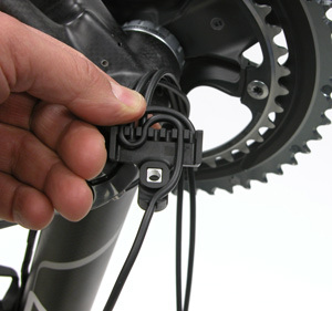
Figure 16. Routing options are performed at the bottom bracket guide
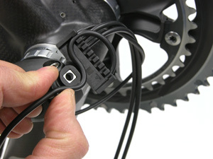
Figure 17. One of several optional routings to change connector wire length
The wire harness guide is bolted to the bottom bracket shell (Figure 18). The best routing options may vary depending upon the bike design. An example of one option is seen in Figure 19. The front derailleur wire and battery connection wire both run between the chain stays. A zip tie holds the wires secure. Each bike is unique, and careful consideration should be given to routing and protection of the wire.

Figure 18. Wire harness guide is bolted in place of conventional bottom bracket guide
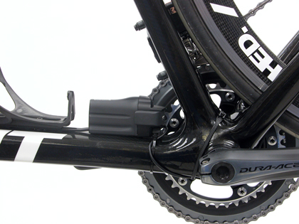
Figure 19. Electrical wires held with zip ties and protected as much as practical
The electrical wire is held down by special adhesive tape pieces (Figure 20). Clean surfaces before installing tape. Place wire onto tape, and then peal off adhesive backing off one side. Place and adhere one side of the tape along the tube, and then peel off the second adhesive backing. Add zip ties as appropriate to increase security (Figure 21).
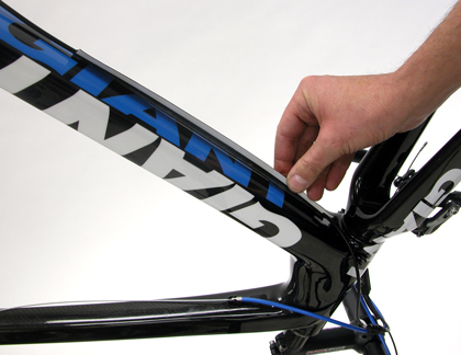
Figure 20. Wires are held to frame by adhesive tape
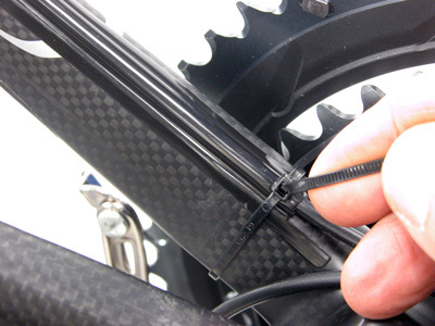
Figure 21. Supplement tape with zip-ties as necessary
Attach the three plugs into each socket receivers of the front derailleur, rear derailleur, and front harness connector. Align the arrow on the plug with the arrow on the receiver and push until the connectors are fully engaged (Figure 22).
Battery Installation
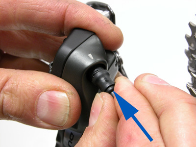
Attach the battery to the battery bracket. The battery engages with the battery bracket rail and then slides into the battery holder. Push the battery fully into holder. Close the quick-release lever to secure the battery (Figure 23).
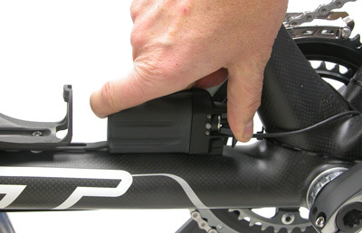
Figure 23. Install battery into bracket and close lever
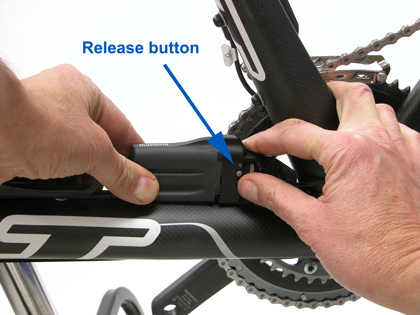
Figure 24. Pull quick-release lever at battery bracket and push release button to remove battery
When charging or replacing the battery, pull the lever on the battery bracket to the open position. Push the release button on the battery and slide the battery out of the holder (Figure 24).
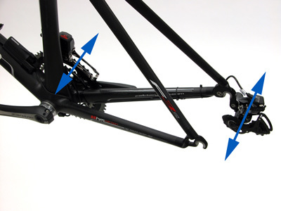
To better understand and appreciate the movement of the derailleurs, do not install the chain or wheel with cassette at this time. Operate front and rear derailleurs and observe movements (Figure 25). Notice as the rear derailleur moves inward, and the front derailleur is on the big ring, the front will trim automatically. When the front derailleur is over the smaller ring, it will trim as the rear derailleur moves outwards. Additionally notice the built in “dwell” of the rear derailleur. Rear derailleur will shift slightly beyond the intended gear, and then settle back under sprocket. This takes the place of a rider “over shifting” the mechanical lever by hand, which pushes the chain beyond the gear, and then allows the chain to settle back down when hand pressure is released.
Leave the rear derailleur positioned over smallest cog and the front derailleur over large ring. Install and size the chain. For sizing purposes only, route the chain over largest rear cog and around largest ring. Pull the chain snug and then add one-inch from the shortest length where it would be possible to join chain. Cut chain and then properly route it through derailleurs.
Shift Adjustment
The shift buttons are housed in the brake levers, similar to the mechanical levers. However, the brake lever blade does not pivot inward as with the mechanical levers. For the rear shifter, there is a button (labeled “switch Y” by Shimano) located on the main lever that will move the chain inward to larger sprockets (Figure 26). For the front shifter the Y switch moves the chain from the small ring to the largest ring.
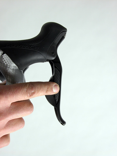
Figure 26. Switch used to move chain to large sprockets (switch Y)
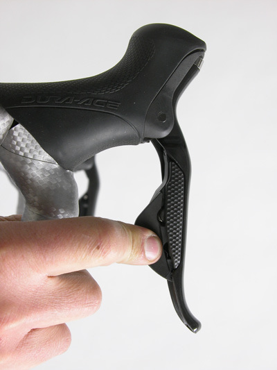
Figure 27. Rear switch used to move chain to outward to smaller cogs (switch X)
The larger switch (labeled “switch X” by Shimano) moves the shifter to smaller sprockets. On the rear shifter this lever will shift from the inner position toward the outer position cogs (Figure 27). On the front shifter, the lever will move the chain from the biggest ring to the smaller ring.
The Shimano RD-7970 rear derailleur uses limit screws on the parallelogram. There is an H and L screw to stop pulley motion. When shifting the rear derailleur do not push the mechanism by hand, as can be done safely with mechanical mechanism. Use the switch to move the derailleur under the smallest rear cog. Look under the derailleur and tight the limit screw to contact the body stops in this position (Figure 28). Test the shift by pedaling and switch the chain between the two outer most cogs.
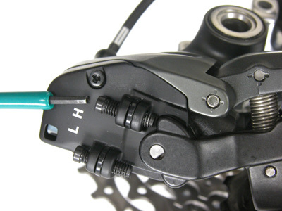
Figure 28. The outer shift limit (H-screw) must contact linkage
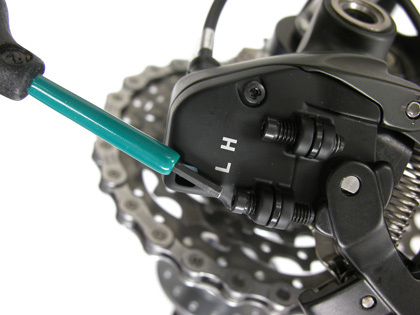
Figure 29. The inner shift limit (L) screw must contact linkage
Pedal and move the chain to the largest rear cogs using the switch. Look under the body and again tighten the L-screw to act as a stop on this cog (Figure 29). Over tightening either limit screw may slow the shift to the extreme cogs.
The B-screw (body screw) setting is the same as on a mechanical unit. Increase or decrease tension as needed until the the upper pulley is close to the largest rear sprocket when the chain is on the smallest front ring.
Fine tune the indexing by using the shifting mode switch on the front wire harness. On a mechanical derailleur, the adjusting barrel is used to effectively length or shorten the housing (“tightening” or “loosening” the cable). This moves the upper guide pulley (the G-pulley) slightly left or right under the cogs and then holds that relative position for all indexing shifts in normal shifting mode.
The index setting method used on the RD-7970 is analogous to the cable barrel adjustment of the mechanical derailleurs, but it is performed by means of small adjustments of the solenoid. Shift the rear derailleur to one of the middle cogs. Push the button at the shift mode switch once and look for the adjustment light to come on (Figure 30). Pressing for a long duration will reset the derailleur from the “safe mode” and will make an audible beep when completed. After pressing the shift adjust button, the lower light will illuminate. The shift mode switch unit will stay in shift adjust mode for approximately 60 seconds. The button can also be pressed again and the light will go off, and the shift mode switch to change to full indexing mode.
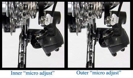
When the shift switch is in adjustment mode, shifting at the lever will move the derailleur a very small amount and then hold that position. The shift adjustment mode precisely positions the pulley inward and outward for 12 “micro shifts”. Each push on the shift lever moves the guide pulley position approximately 0.2mm (Figure 31). The entire range is approximately 4.8mm from innermost to outermost adjustment positions. The derailleur and shifting system holds that adjustment when returned to full index shifting mode.
Pedal the bike and sight the upper pulley relative to the cog (Figure 32). If there is a rattle from the chain of the chain being too far in or out, make the appropriate adjustment at the lever, pushing lever only one or two times, and then checking again.
Press the shift mode button again and the shift mode switch will change back to normal shifting mode. Shift to other gears and test the setting. If further adjustments must be made to index, again press the shift mode switch to get back to “indexing mode.”
Front Derailleur Adjustments
The front derailleur uses a strong solenoid to move the cage from inner to outer positions. Work with care to not crush fingers between cage and ring while shifting. The adjustment screws of the braze-on model are shown in Figure 33.
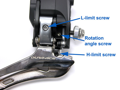
Figure 33. Location of adjustment screws
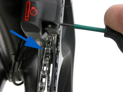
Figure 34. Inspect the gap between chain and cage
During installation, the lower edge of the cage should be set approximately 2mm over the largest chainring. Unlike the rear derailleur, the front derailleur can be pulled by hand outward to set height. Set the L-screw to the small ring by first shifting the rear derailleur to the largest cog. This will trim the front cage inward. Turn the limit screw clockwise to move the cage outward until the inner cage of the derailleur begins to contact the chain, and then loosen until there is a slight gap between the chain and inner cage (Figure 34).
To set the H-limit screw, shift the rear derailleur to the smallest cog, and shift the front derailleur to the largest chain ring. The H-screw is underneath the linkage. Turn the H-screw clockwise to move the cage outwards. Turn the H-screw counter-clockwise to move the cage inward (Figure 35). This may seem counter-intuitive to mechanics accustomed to cable operated front derailleur systems.
Battery and Electronics
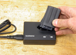
The lithium ion battery will require recharging with use as the battery will drain with time and after a number of shifts. The charger (Shimano SM-BCR1) is a dedicated unit for this system, and should not be used for other batteries (Figure 36).
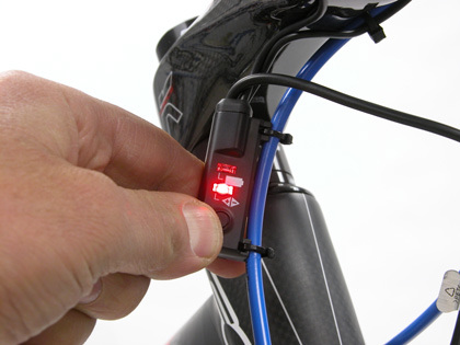
There are two places to check the remaining battery charge. One is the flight deck display at the handlebar harness. A second method is to press and hold any shift switch until an indictor light comes on at the handlebar harness. The upper indicator light will flash when the button is pressed. A full battery charge will show a green light for 2 seconds. A 50% battery charge will flash green five times (Figure 37). A 25% battery charge will illuminate red for only 2 seconds. A battery with effectively 0% charge will flash red five times. If there is no charge in the battery, the derailleurs will stay in the last gear they were shifted to.
The battery may take approximately 1.5 hours to fully charge, and the orange charging indictor light will turn off.
Shimano offers a diagnostic electronic system checker for the Di2 system. This is item number SM-EC79 and is available from Shimano (Figure 38).
When disconnecting the sockets from the receivers never pull directly on the wire (Figure 39). Use the special tool to leverage the plug out of the socket (Figure 40).
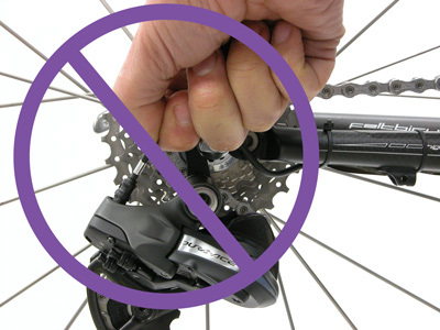
Figure 39. Never pull directly on wire
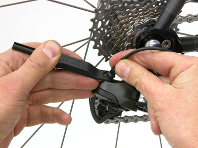
Figure 40. Use Shimano TL-EW01 tool to pry out socket
Crash Feature
The rear derailleur has a built-in protection feature to help in case of a crash. During an impact, the connection between the solenoid and the parallelogram opens, and the rear derailleur will no longer operate. This is designed to protect the system, for example, when the bicycle falls over. To reset the system, press the button on the handlebar switch (SM-EW79A) for at least five seconds to re-connect the solenoid to the parallelogram. Double check the shifting and fine tune the derailleur, using the shift adjust mode as necessary.
Related articles
Front Derailleur Adjustment View Article
Rear Derailleur Adjustment View Article
Rear Derailleur Hanger Alignment View Article
Chain Replacement: Derailleur Bikes View Article
Shift Levers / Shifters View Article