1951-15 Adapter Stud Installation for PRS-15
This article demonstrates how to disassemble your PRS-15 repair stand to replace the original 100-15X clamp with the 100-25D micro-adjust clamp using the 1951-15 adapter stud.
Preliminary Info
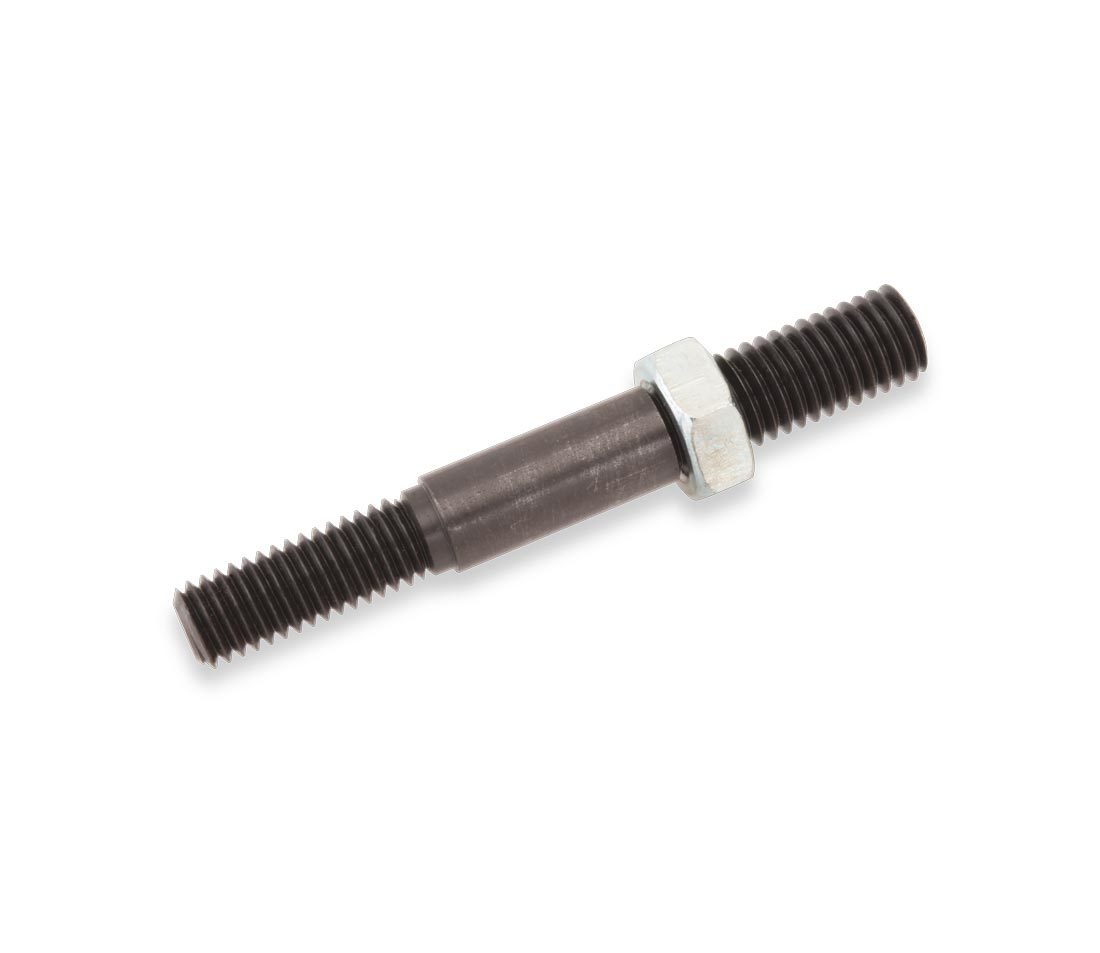
The #1951-15 is a threaded stud that adapts the 100-25D to fit the PRS-15 repair stand (figure 1). Before beginning the process of replacing it’s important to take note of a couple important points.
One notable difference is that the 100-25D clamp will not fold downward as with the original 100-15X clamp design. Additionally, the #1951-15 adapter stud works only in PRS-15 stands with three-pointed clamp knobs.
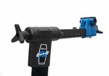
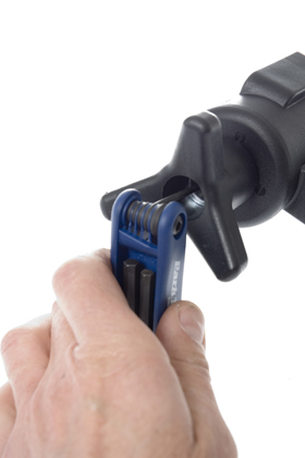
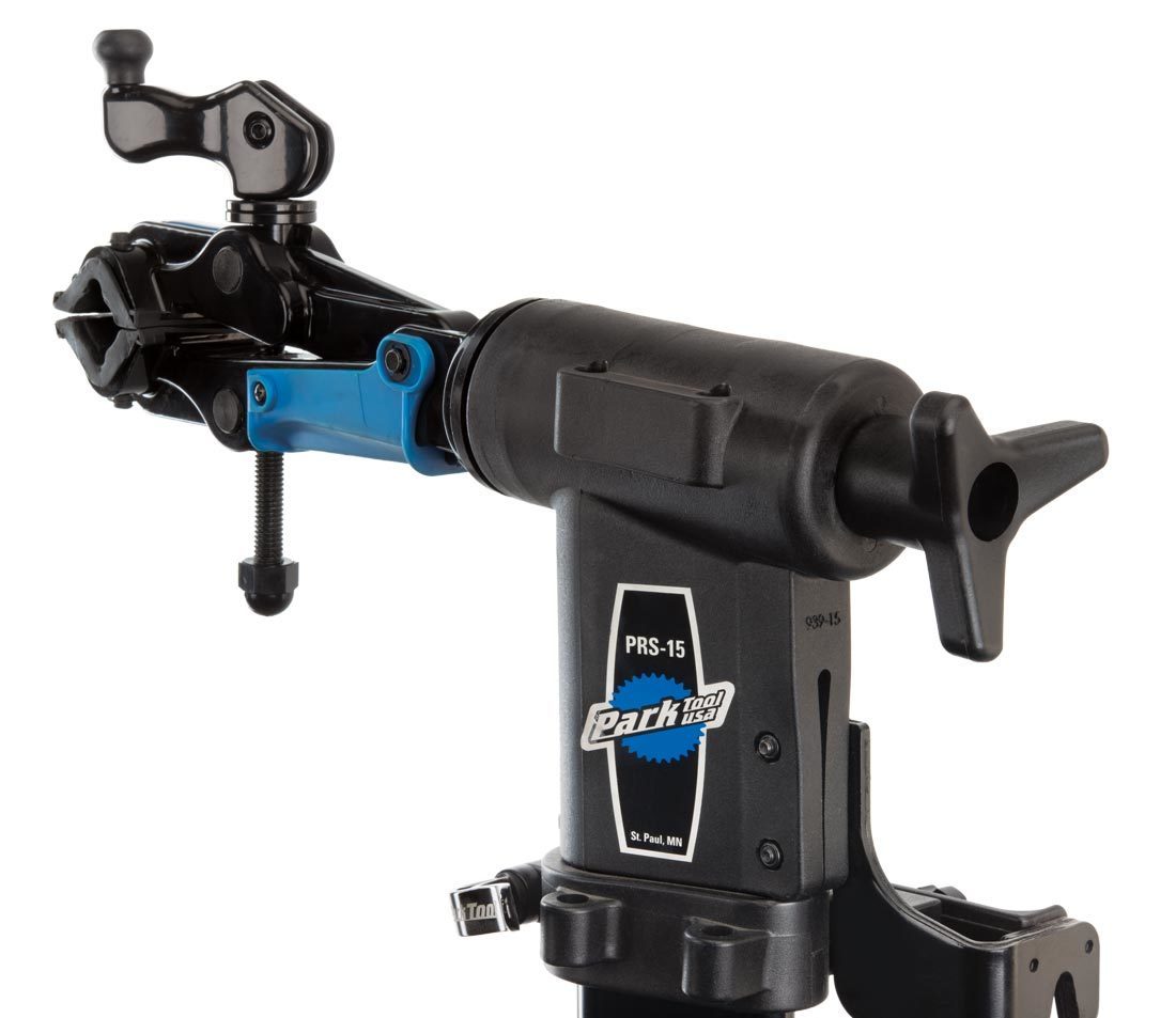
First-generation PRS-15 models use a single, long handle to secure the clamp from rotation (figure 2). On these models, the three-pointed handle (part #1233) must also be added for the 1951-15 adapter stud to work with the 100-25D (figure 3).
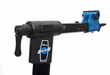
Figure 2. The first generation top tube levers will not work with 1951-15 adapter studs
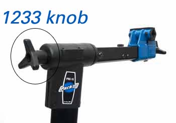
Figure 3. The 1233 top tube knob is necessary for the 1951-15
100-15X Removal
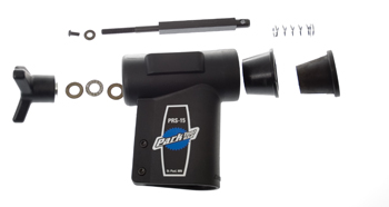
To install the 1951-15 and 100-25D clamp, begin by removing the 100-15X clamp and handle assembly (figure 4).
- Loosen and remove the top tube knob screw and washer (figure 5). NOTE: This is a left-hand threaded screw and is installed with a threadlocker. Use mild heat from a hair dryer or air gun. Remove by turning clockwise.
- Unthread knob completely from main clamp screw.
- Remove clamp and parts from top tube (figure 6).
100-25D Installation
- Use from the previous parts the knob, two thrust washers, and the one thrust washer bearing. Clamp thread and top tube tapered sleeves from the 100-15X will not be used with the 100-25D.
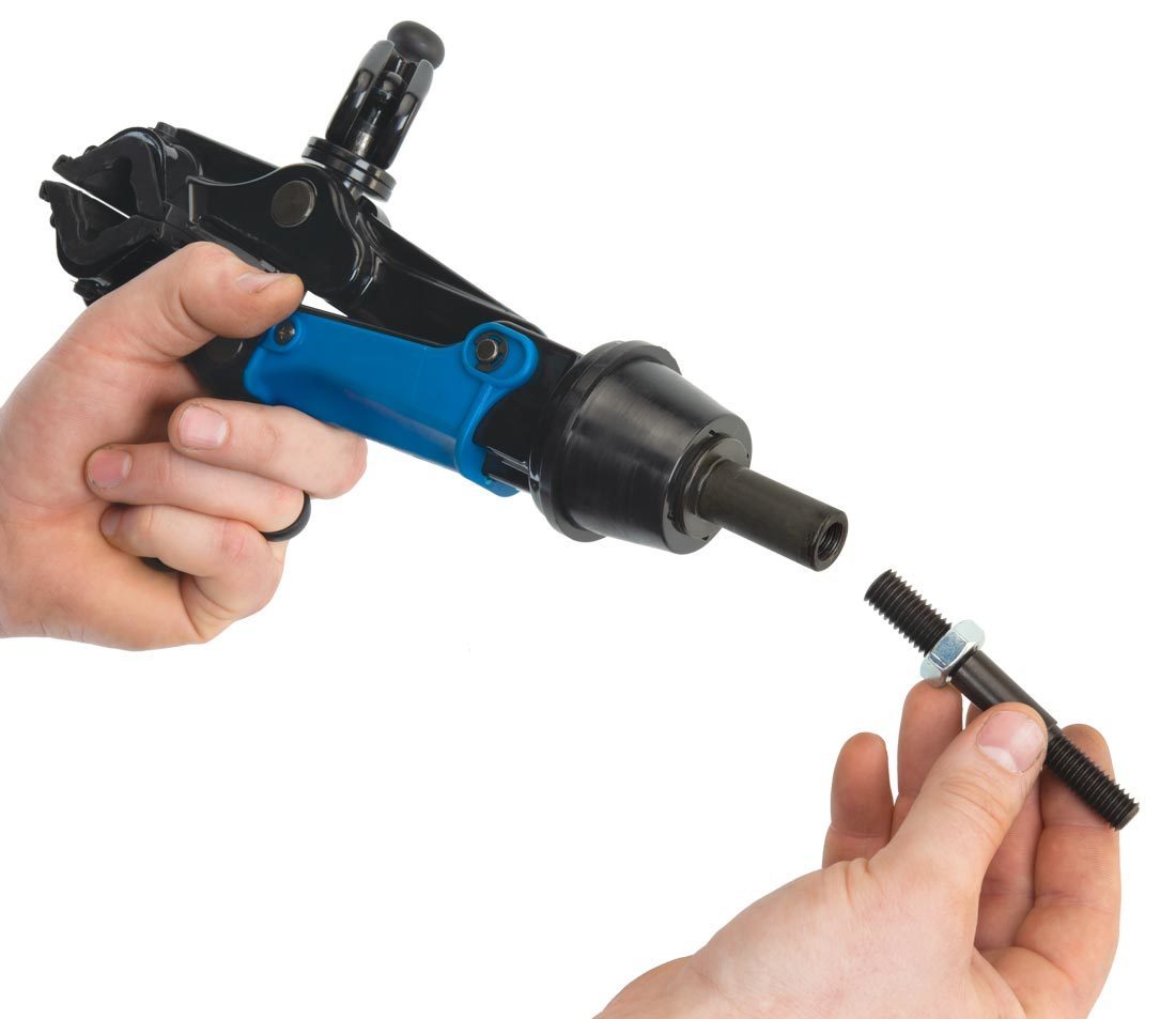
- The 1951-15 has two threads, one side in 1/2″ and the other a smaller 7/16″ thread (figure 7). Install the 1/2″ jam nut onto the 1951-15. Thread the larger 1/2″ thread into the back of the 100-25D clamp (figure 7).
- Tighten the jam nut against the 100-25D (figure 8).
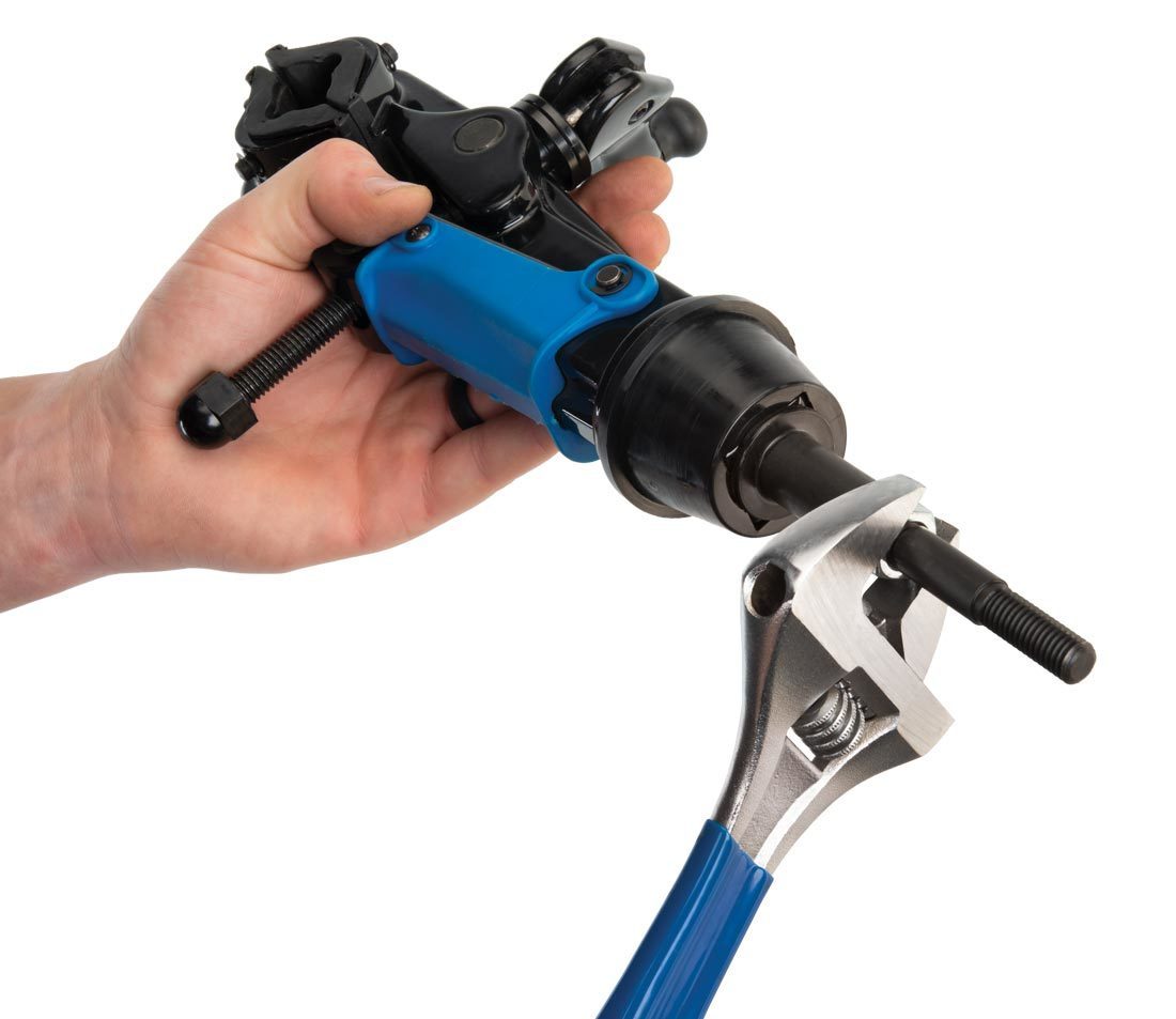
- Place the 100-25D through the top tube (figure 9). The 7/16″ thread will protrude through the back of the top tube. Install one thrust washer, the thrust bearing, and then the other thrust wash on the thread (figure 10).
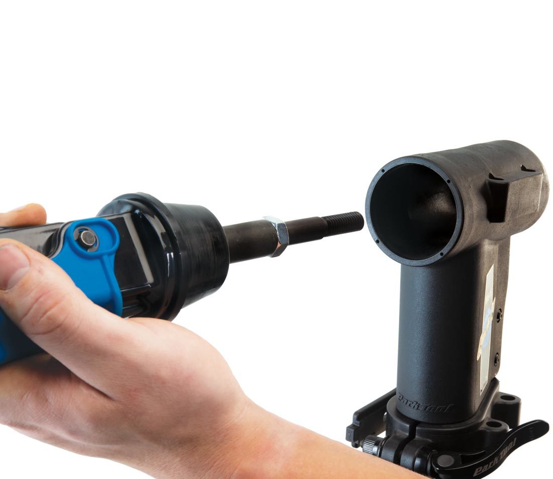
Figure 9. Insert the 100-25D into the top tube
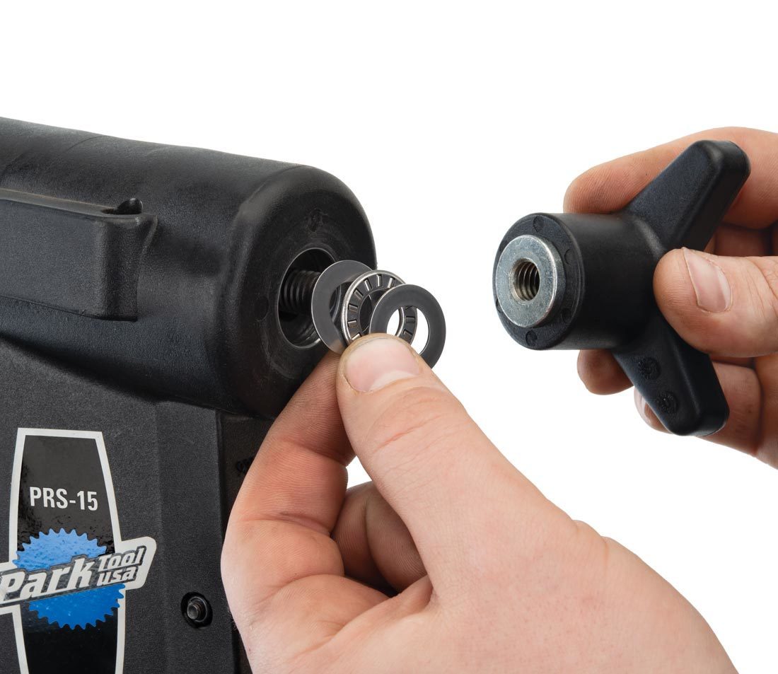
Figure 10. Assemble the thrust washers and bearing
- Thread the knob onto the thread and secure. To rotate, loosen knob to free clamp in top tube. Clamp is installed and ready for use (figure 11).
NOTE: There is no stop built into the knob assembly. Use care not to unthread the knob too far. Unthreading the knob completely will allow the clamp and any bike to fall out of the stand.
Related articles
100-4X, 100-15X & 100-6X, and PRS-15 Service View Article