NuVinci® N360® Hub Installation and Adjustment
This article reviews the installation and adjustment of the NuVinci® N360® CVP rear hub and shifting system. The order of procedures to follow will vary depending upon whether you are installing a new system or servicing a previously install hub.
Getting Started
Fallbrook Technologies offers an interesting rear hub system under the name NuVinci™ N360®. This hub uses a Continuously Variable Planetary (CVP) transmission to drive the wheel. Internal transmission systems have been on the market from other manufacturers in systems offering from 2 speeds to 10 speeds for almost a century. Traditional internal gear systems rely on a planetary gear system of tooth rings and gears. Planetary gear systems produce distinct gear ratios as the rider shifts up and down the gear system. The CVP system of the NuVinci™ N360® does not produce these distinct changes. The gear ratios seem to “slide” as you turn the shifter grip. Consider this system to be the slide trombone of the shifting orchestra, or if you prefer, the whammy-bar. It is difficult to describe without actually riding it, but especially the novice rider will immediately understand how it is to be used. Directions for use are simple: Ride bike, twist shift, be happy.
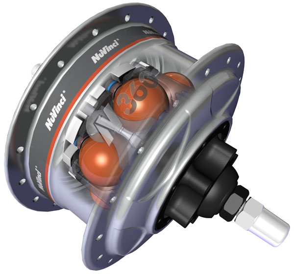
The hub where the gear changes take place is not considered user serviceable, or even accessible. If the system requires internal work it should be returned to the manufacturer. The NuVinci™ transmission uses a set of rotating and continuously variable-tilt balls positioned between the input and output components of the transmission to vary the input-output ratios of the transmission (figure 1). A shifting idler and a special transmission fluid transfer the torque of the input (the chain-driven sprocket) through these balls to the output of the transmission (the wheel).
The NuVinci™ N360® hub has a relatively wide range of gearing options. The gearing starts with the front chain ring and rear sprocket selected. This produces a gear ratio that would be equal to a one-speed bike with no internal gearing. Assume for this example it is a 42 front ring with a 18 tooth rear cog (42 x 18). One pedal revolution produces 2.33 revolutions on the rear wheel. The NuVinci™ 360 will reduce this by half (0.5) or increase it by a factor of 1.8. In the “underdrive” range one pedal revolution will produce 1.17 wheel revolutions, and the “overdrive” will produce 4.2 revolutions.
Many cyclists think in terms of the sprockets selected. If this were a multi sprocket bike it would be approximately equal to having only the 42 front ring and a rear cassette range from a 10 tooth cog to a 36 tooth cog. That is a very wide gear range, but with the NuVinci™ you also get every gear in between, not just the range divided into 9 or 10 choices. Enough of this long winded explanation; simply go ride it. You must feel it to know it.
Video 1. Shifting the NuVinci™ 360 hub
Shift Lever and Shift Cable Installation and Removal
The NuVinci™ uses a single twist-style shifter. It may be used on either left or right side; however the shift display is intended to be mounted on the right-hand side. The shifter fits a 22.2mm diameter flat handlebar end. If used on mustache or drop-style handlebars, it will require an adapter, to reduce the diameter of the clamping surface so the shifter may be mounted.
The shifter operates two shift cables that run through two separate housings to the shifting mechanism at the rear hub. As the shifter is rotated it will pull on one cable to turn the shifting mechanism, called the “hub-interface”. Rotating the shifter the opposite way pulls the other cable. Housing lengths should be sized like any other cable housing. Housing should not be longer than necessary but still enter the housing stops in a straight line. A typical after-market installation will require full housing from the shifter to the hub-interface.
Replacing Shift Cables
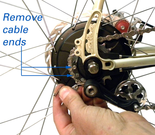
- Remove both cable fittings from the hub-interface (figure 2).
- Loosen setscrew fittings on both cables. Pull cable ends free from the hub-interface. Use care not to lose setscrew fittings.
- Rotate the shifter so the bottom cover plate faces upward. Shifter-handlebar setscrew is located under shifter.
- Use a small cross tip screwdriver to remove the shifter mechanism cover screw. Carefully pull up on plastic cover and remove (figure 3).
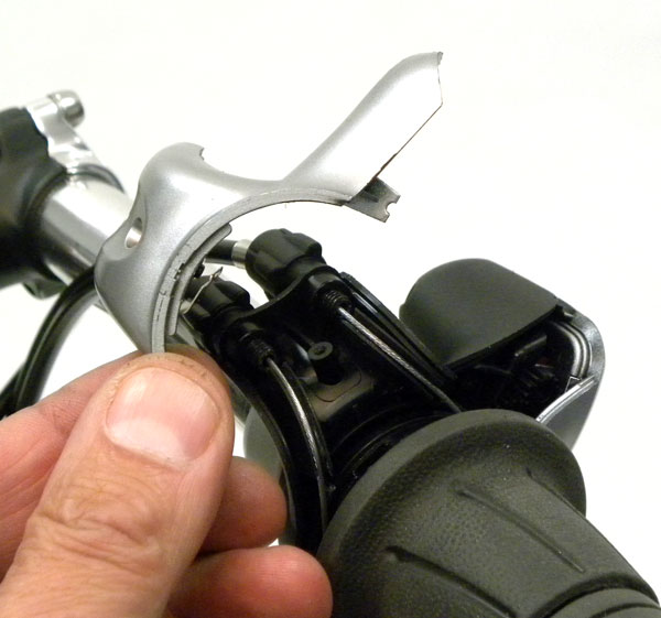
Figure 3. Remove Shifter Cover
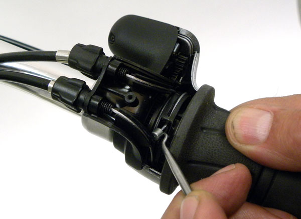
Figure 4. Use seal pick to left and remove cable end
- There are two cable ends fitted in the shifter. Rotate shifter turning grip until one cable end is visible. Use a seal pick to remove one cable end (figure 4). Pull cable from housing.
- Rotate shifter the opposite direction to expose second cable end. Use pick to remove cable.
- Pull second cable end and remove cable from shifter.
Installing New Cables
- With shifter cover plate removed, rotate shifter turning grip fully one direction to expose cable end socket.
- Give cable end a slight bend and feed into cable socket approximately 1-2cm. Rotate shifter turning grip and cable together. Push on cable until cable becomes visible as it wraps around turning grip barrel.
- Feed cable end through barrel adjuster and into cable guide of shifter (figure 5)
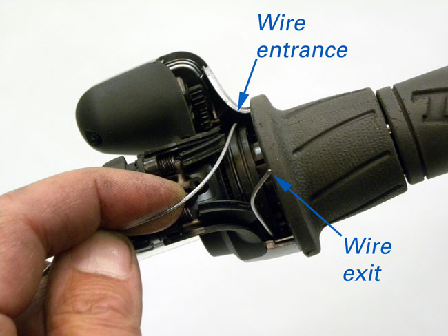
Figure 5. Guide wire through shifter and out opposite side
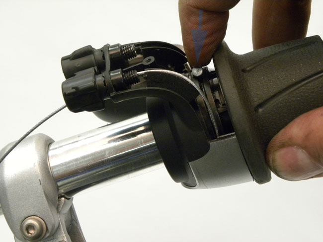
Figure 6. Push cable end into shifter seat
- Pull cable and seat cable end into shifter cable end seat (figure 6).
- Rotate shifter turning grip to expose second cable seat.
- Repeat process of installing cable.
- Reinstall cover plate and secure cover plate screw.
- Return shifter to normal position and secure shifter-handlebar setscrew.
For a review of cable removal and installation see the video below (video 2).
Video 2. Cable removal and installation
Cable Attachment to Hub-Interface
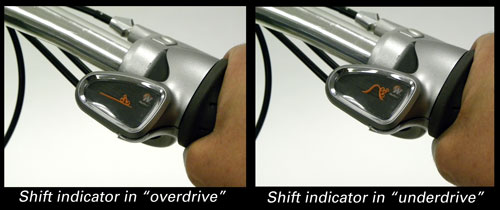
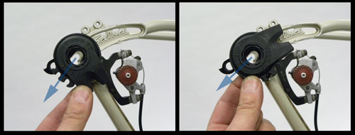
Pulling on the “overdrive” cable pulls the cable into the housing at the hub end, and rotates the hub-interface. The “underdrive” cable is extended fully when this is done. Twisting the shifter turning grip back will pull the “underdrive” cable into the housing and the “overdrive” cable will extend from its housing at the hub end. The hub-interface moves into the low gear range. The shifter has a flexible indicator that shows a cyclist climbing a hill in the underdrive mode. The cyclist indicator line flattens for the overdrive mode (Figure 7).
- Route each shift cable through housing pieces and seat the housing ends into shifter barrel adjusters.
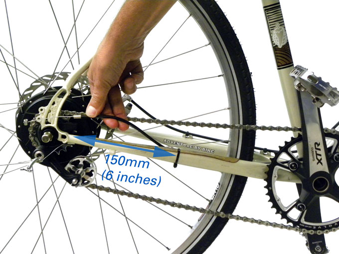
- Zip-tie housing securely along frame and along chain or seat stay as desired. Leave approximately 6″ (150mm) of free housing before the hub-interface (figure 8). This will permit the housing to be removed and installed into the hub-interface.
- Pull the end of the “underdrive” cable to extend it as much as possible out of its housing at the hub end. This will pull the “overdrive” cable into its housing at the hub end. Check that the shift indicator shows the rider in the flat (overdrive) position.
- Measure the exposed wire between the cable ferrule and the 4mm diameter cable stop fitting for a distance of 117mm (or between 115 to 117mm) (figure 9). This can be an awkward to measurement to make accurately. One way to do this is to cut a piece of scrap housing to 117mm (figure 10). Slip the housing over the wire, and use a permanent marker to mark the wire.
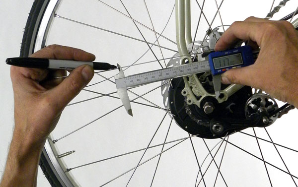
Figure 9. Measure 117mm of exposed wire for underdrive cable
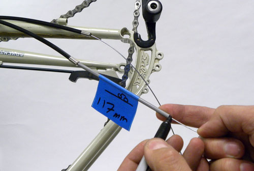
Figure 10. Use scrap housing to measure the correct distance and mark shift wire for cutting
- Remove the measuring-housing and run the 4mm diameter underdrive cable stop fitting up to the end of the ink mark.
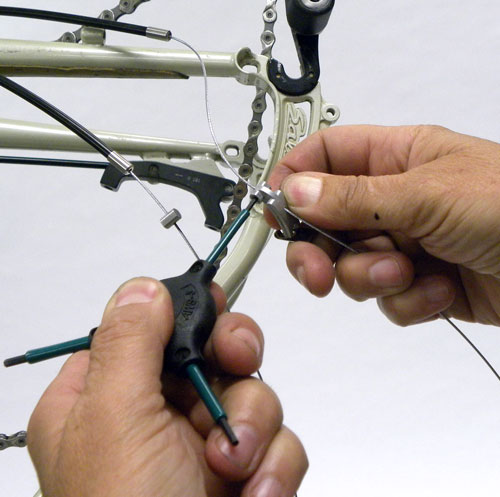
- Hold cable stop fitting with a small adjustable wrench and secure the setscrew to hold the cable (figure 11).
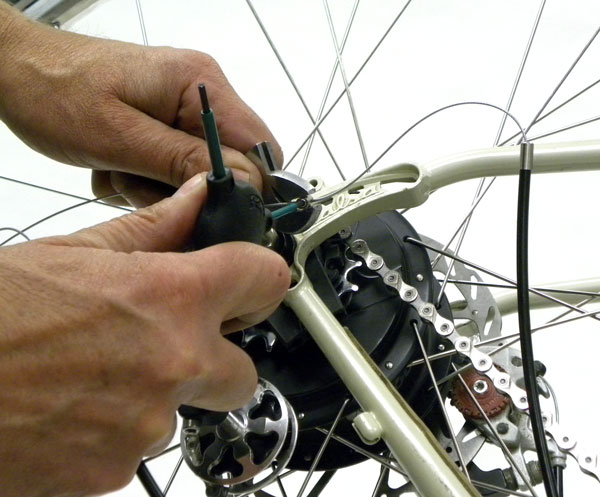
Figure 11. Secure shift cable fitting
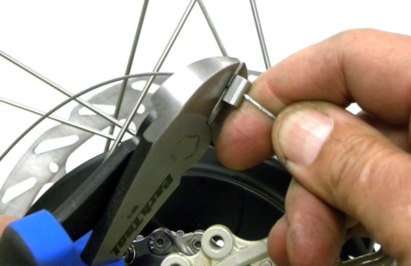
Figure 12. Flush trim underdrive shift wire to leave no more than 2mm of wire extending past the fitting
- Cut excess cable extending beyond the fitting flush with the fitting so that no more than 2mm of cable extends past the fitting (figure 12). No cable end cap is used here. Cable stop must fit inside ratio-selector of the hub-interface.
- Pull the “overdrive” cable to extend it from the housing until it stops. This will then shorten the exposed “underdrive” cable at the hub end of the housing to its maximum extent. Check the shift indicator show the “rider” to be in an extreme uphill climbing position (figure 13).
Figure 13. Shift indicator showing underdrive mode
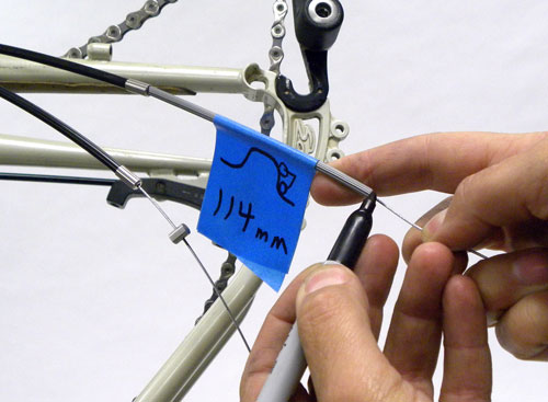
Figure 14. Measure and mark cable for placement of cable latch
- Run cable through overdrive latch and measure the exposed wire to be a length of 114mm. Again, it is useful to cut a piece of scrap housing to 114mm and use this to measure and mark the overdrive cable at the correct length (figure 14).
- Remove the measuring-housing. Install the cable through the hole in the overdrive cable latch and adjust the position of the latch to just cover the ink mark (figure 15).
- Secure setscrew in cable latch. Cut excess cable approximately 1/2″ to 1″ beyond and secure cable with end cap.
Installation and Alignment of Hub-Interface
Like other internally geared systems, the NuVinci™ relies on no-turn (keyed) axle washers to prevent the axle from turning in the dropouts (figure 16). The hub gearing systems drive off the axle and the axle must be locked securely from rotation. The hub axle has two flats that mate into the non-turn washers. The tab on the no-turn washer will point to the opening in the dropout, and will also provide a reference for alignment of the hub-interface.
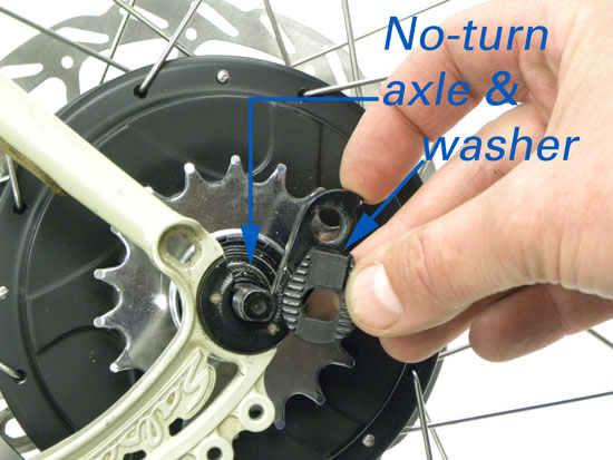
Figure 16. No-turn washer and axle
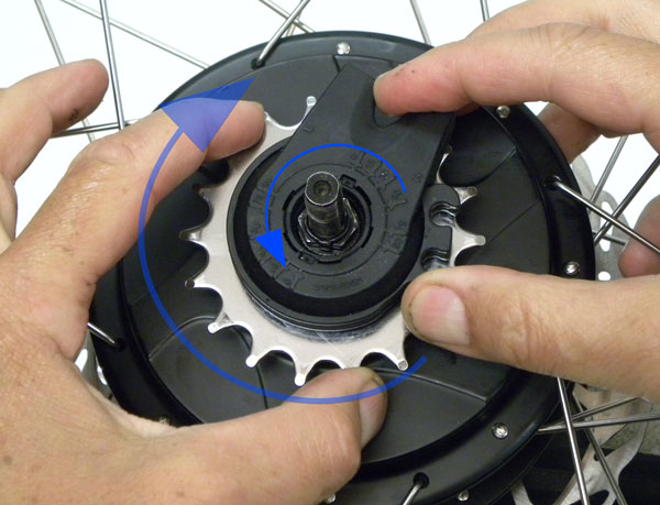
Figure 17. Set the NuVinci™ hub to full overdrive
It is necessary to have the hub idler control splines set to full overdrive. Do this by mounting the left side axle secure in an axle vise. Install only the hub-interface in any orientation. DO NOT install the knurled interface washer for this adjustment. Rotate the wheel and sprocket clockwise while at the same time turning the hub-interface body counterclockwise (figure 17). To test the setting, remove the hub-interface. Note the position of the valve on the wheel and the position of the sprocket. Turn the sprocket clockwise one complete turn while counting the rotation of the rim. The rim should rotate 1.8 to 2 revolutions to a single revolution of the sprocket.
The hub and wheel are now ready to for mounting of the hub-interface. If it is observed that the hub-interface is not correctly aligned to the bicycle frame dropout when the non-turn washer is installed, the hub-interface must not be rotated relative to the axle. Rotating the hub-interface will change the range of available gear ratio. The wheel must be removed and hub-interface repositioned the correct spline options. See video 3 for a review.
Video 3. Setting the hub to overdrive and installing the hub-interface
To remove the hub-interface, remove axle nut and the non-turn washer. Use a small tipped screwdriver to remove the knurled hub washer from inside the hub-interface. Next gently pry up on the hub-interface and lift if from the axle.
Positioning of Hub-Interface
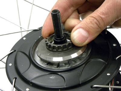
All of the action of the hub takes place at the hub-interface, and the placement and alignment of this piece is critical to the workings of the system. The hub-interface moves the idler inside the hub shell by turning the shift-driver seen on the right side of the hub axle. The hub-interface uses a series of splines to mate with the shift driver splines (figure 18).
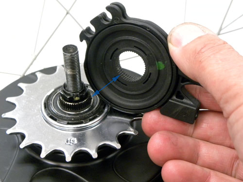
Figure 18. Shift driver and hub-interface
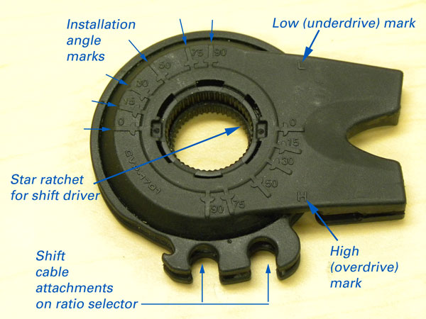
Figure 19. Hub-interface that rotates the shift-driver
The hub-interface consists of several parts, and is actually a planetary system itself. The body of the hub-interface is bolted securely and does not rotate in operation. The shift cables pull on the ratio-selector to rotate between the Low and High gear marks, and this turns the inner star ratchet. The hub-interface star ratchet will rotate the shift-driver on the hub.
Alignment of Hub-Interface
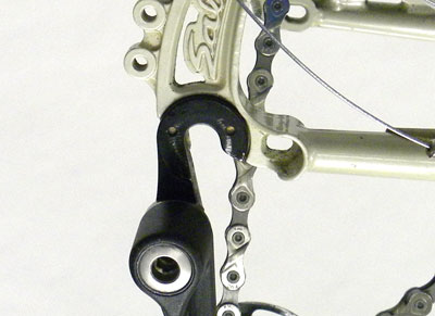
It is important the hub-interface be aligned at the dropout to allow the cable housings correctly the approach the hub. It is generally best to route the housing along the chain stay or seat stay (figures 20 and 21). This protects the housing, provides a cleaner look and keeps housing from flopping around into the spokes (figure 22).
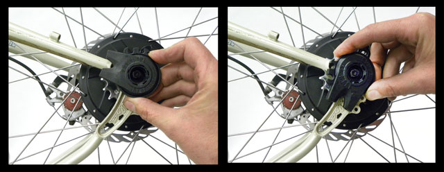
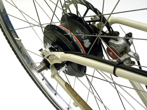
Figure 21. Seat stay routed option
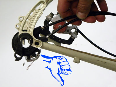
Figure 22. Inappropriate alignment of the hub-interface. Reposition to route along stays.
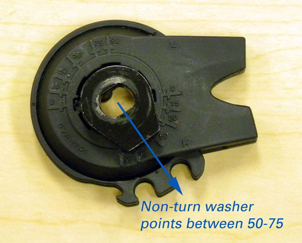
The non-turn washer will sit in only one position in the dropout and the hub-interface must be aligned relative to this position. The hub-interface can be rotated in approximately 8-degree increments around the shift-driver. The hub-interface is stamped with angle reference number to assist in alignment (figure 23).
The axle flats and the non-turn washer are used as a reference to correctly orient the hub-interface (figure 24).
The non-turn washer will align with the opening of the dropout. The three common options for the dropouts are the horizontal dropout (figure 25), the rear-exit dropout (figure 26) and the vertical dropout (figure 27).
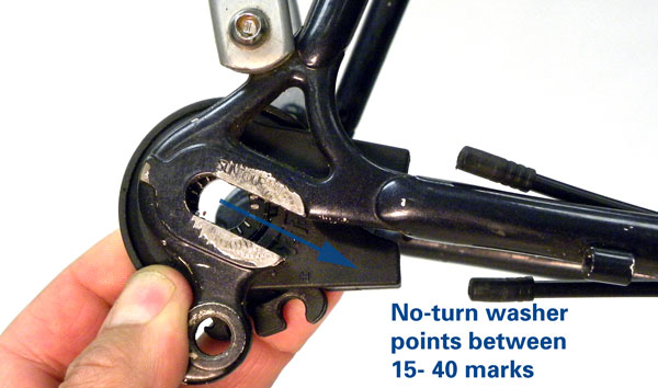
Figure 25. Estimating the position on a forward facing dropout
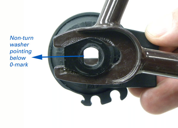
Figure 26. Rear facing dropout
Video 4 reviews the alignment and function of the hub-interface.
Video 4
Installing Rear Wheel
The rear wheel is installed only when the hub-interface is correctly positioned.
- The shifting adapter, non-turn washers and axle nuts should be installed on axle.
- Install chain over sprocket and engage axle into bike dropouts. Pull wheel fully into dropout.
- Rotate the axle using the non-turn washers so the washer tabs are pointed the dropout exit. Seat axle washers into dropouts and inspect hub-interface.
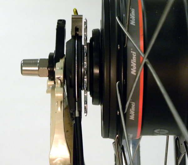
- When the wheel is mounted, inspect hub-interface. It must not contact or press against the frame or stay. Inspect for clearance between frame and hub-interface (figure 28). It may be necessary to rotate hub-interface to prevent contact.
- If hub-interface is incorrectly aligned the wheel must be removed and the hub-interface reinstalled to a better alignment using a new combination of splines on the star ratchet and the shift driver. DO NOT attempt to realign the hub-adapter by loosening the axle nuts, rotating the hub-interface, and retightening the axle nuts. Rotating the hub-interface on the driver without uninstalling it will change the available gear ratios.
- Secure axle nuts to 266 to350 inch pounds torque (30-40Nm).
Shift Cable Attachment to Hub-Interface
To install cable, it is easier to rotate the ratio-selector for better access. Push the mechanism clockwise while pedaling slowly (figure 29).
- Install underdrive cable in the upper housing stop of the hub-interface.
- Pull on the underdrive cable to get as much slack as possible (figure 30). This will pull the overdrive cable into the housing.
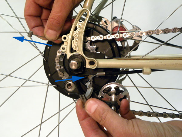
Figure 30. Pull overdrive cable
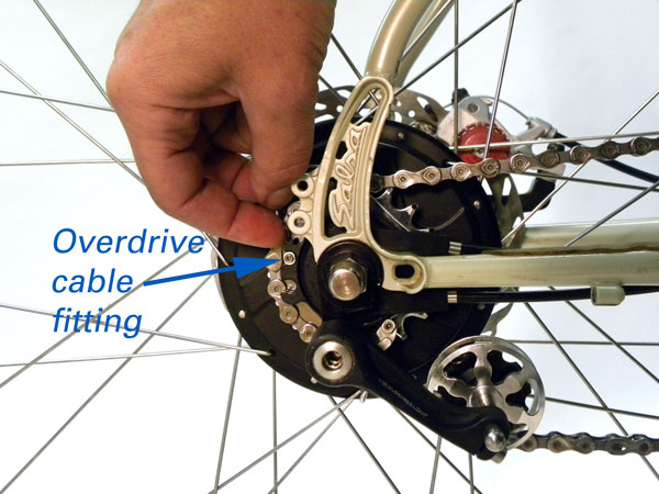
Figure 31. Engage fitting into ratio-selector
- Install overdrive cable fitting into most clockwise receiver of ratio-selector (figure 31).
- Pull on underdrive cable. This will pull the overdrive cable into the housing and seat the overdrive cable in the ratio-selector. Engage the overdrive cable into the most counter-clockwise fitting of the ratio-selector.
- Push overdrive cable latch into locked postion (figure 33).
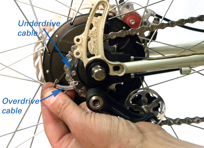
Figure 32. Engage overdrive latch onto ratio-selector
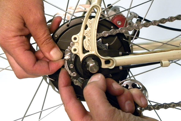
Figure 33. Snap latch closed
- Test gear adjustment by pedaling bike and shifting the hub-interface through the entire gear ratio range. The ratio-selector should rotate fully toward the High gear position when the shift indicator is in “flat” mode configuration (figure 34).

Figure 34. Full overdrive mode
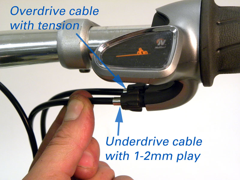
Figure 35. Check play at underdrive cable
- Check shift housing to barrel adjuster play. The overdrive cable will have tension. However, the underdrive housing (rear facing) should have a slightly amount of play between end cap and barrel adjuster (figure 35). Use barrel adjuster to adjust, but do not over-tension the underdrive cable as this will prevent shifting through the full range of ratios.
- Pedal bike and shift turning grip on the shifter to underdrive and inspect the ratio-indicator on hub-interface (figure 36). The underdrive cable will now have tension. The overdrive housing (the forward most housing) should have a slight amount of play between end cap and barrel adjuster (figure 37). Use barrel adjuster to adjust, but do not over-tension the overdrive cable as this will prevent shifting through the full range of ratios.
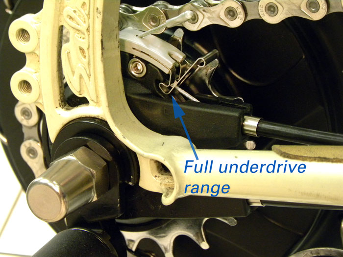
Figure 36. Underdrive mode
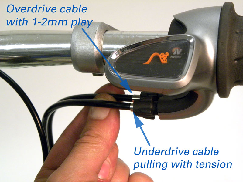
Figure 37. Check play at overdrive cable
Removing Rear Wheel
When the rear wheel is removed from the bike, it is necessary to remove the cables from the hub-interface. If the wheel is being removed for tire or tube service, or wheel truing, there is no need to remove the hub-interface or shift adapter washer.
If the intended service requires removing the hub-interface, begin by inspecting the interface at the rear dropout. If the hub-interface is correctly aligned, make note of the position of the non-turn washer as it points to the hub-interface markings.
Procedure to remove cables from the hub-interface:
- Shift bike to overdrive, with the Shift Indicator Rider in the flat terrain position.
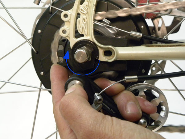
- Release Overdrive Cable Latch and pull back until fitting is able to exit hub-interface ratio-selector (figure 38).
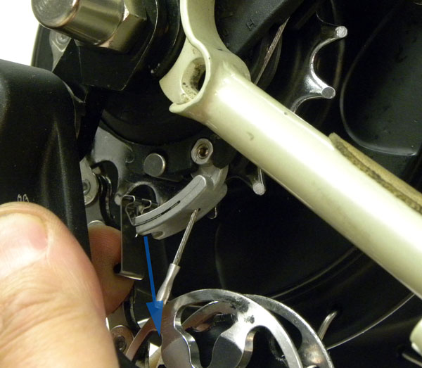
Figure 38. Release cable latch first
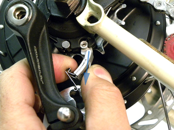
Figure 39. Pull cable latch out of ratio-selector
- Pull on the housing for the overdrive cable to remove housing from the hub-interface (figure 39).
- Rotate shifter part way toward Underdrive mode, with Shift Indicator Rider on hill.
- Pull back on Underdrive housing and remove housing from its seat in hub-interface (figure 40).
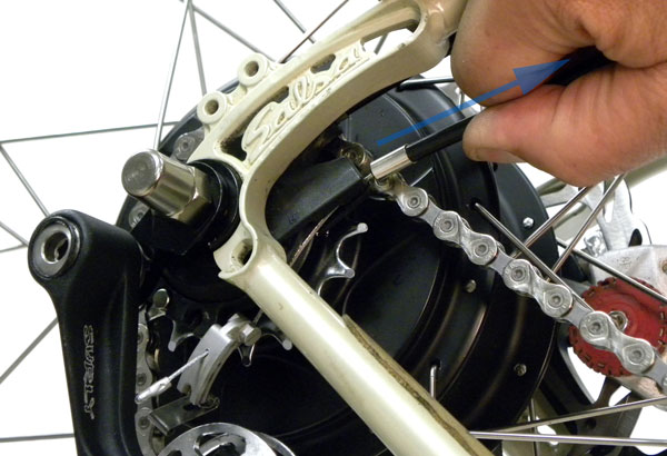
Figure 40. Remove housing from hub-interface
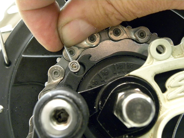
Figure 41. Release cable fitting from ratio-selector
- F. Pull Underdrive cable to get slack and release underdrive cable fitting from ratio-selector (figure 41).
- G. Both cables should now be free of hub-interface. Loosen axle nuts and remove wheel. NOTE: Wheel will have some weight. Be prepared to support wheel as it exits bike. A good alternative is to rotate bike and work with bike upside down and frame dropouts facing upwards (figure 42).
Rear Cog and Freehub Service
The rear hub uses a “freehub” system to hold the single speed cog. The single sprocket is a 9 splined Shimano-compatible BMX style that uses 3/32″ chain (derailleur chain). NuVinci™ provides a freehub rebuild kit including new snap rings and needle bearings.
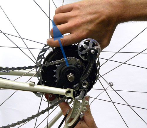
- Begin by removing the hub-interface. Lift the shift adapter using a small tipped screwdriver (figure 43).
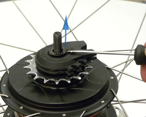
Figure 43. Remove shift adapter
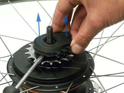
Figure 44. Lift and remove hub-interface
- Lift the hub-interface using a wider flat bladed screwdriver under the unit, gently prying it upward (figure 44).
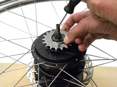
- The sprocket is held by a snap ring. Use a small screwdriver to lift off the snap ring and remove the cog (figure 45).
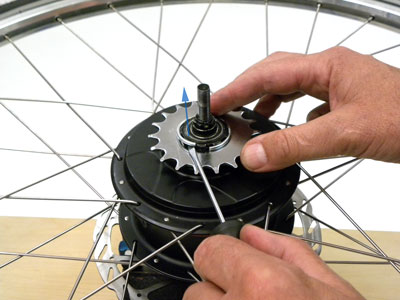
Figure 45. Remove snap ring from rear cog
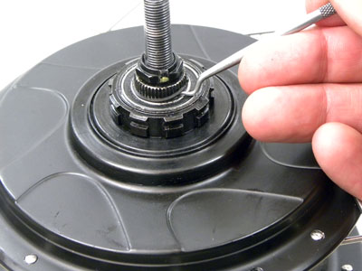
Figure 46. Remove snap ring
- The freehub body is held by a small snap ring. Use a seal pick or small tipped screwdriver to remove (figure 46).
- The freehub body lifts off to expose the hub star ratchet and a needle bearing. A snap ring holds the needle bearing in place and may be removed with a pick (figure 47).
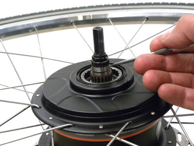
Figure 47. Remove snap ring

Figure 48. Parts of the freehub system
- The parts may now be cleaned and re-greased (figure 48). There is a cartridge bearing inside the hub. Do not attempt to remove this bearing. Any further service work should be performed by Fallbrook Technologies.
The seal may be lifted and grease applied to the bearings. However do not attempt to flush the axle bearings with any solvent. Solvent will work its way into the hub shell and cause problems with the hub internals. - Reverse the procedure to reassemble the freehub. Install the rear cog snap ring (figure 49).
N360 Hub Braking System Interface
There are three possible hub adaptations for rear brakes in the NuVinci™ system. The hub will accept a six-bolt rotor mount, a roller brake mount, or a simple cap for rim brakes. To change the hub configuration, begin by removing the left side locknut. Hold axle in an axle vise and turn nut counter-clockwise (figure 50). There is a spacer washer under the locknut.
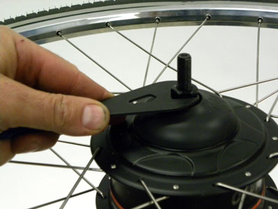
Figure 50. Remove locknut and spacer
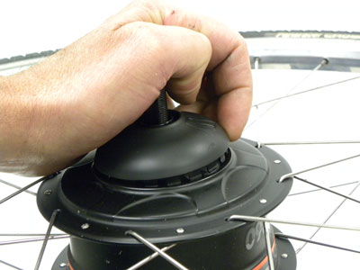
Figure 51. Remove plastic cap
If the wheel is intended for use with a rim brake, there is a simple plastic cover. Pop this cover up using only your hands (figure 51).
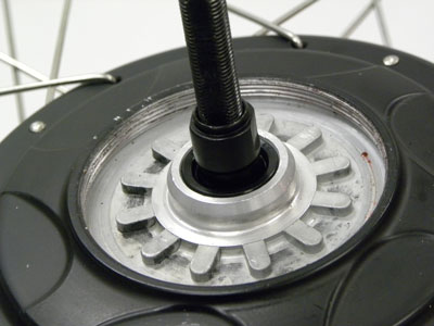
There is no cone below this locknut. The axle rides on cartridge bearings. There is no service beyond this point. If there is a problem with the hub or with the axle, it must be returned to the manufacturer for service (figure 52).
The left side is fitted with threads in the hub shell for a lockring. This ring will hold the rotor mount and the roller brake mount secure to the hub shell. Fallbrook Technology supplies a proprietary pin tool to remove and secure this ring (figure 53 and 54).
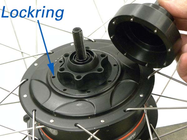
Figure 53. Rotor disc mount with lockring ring
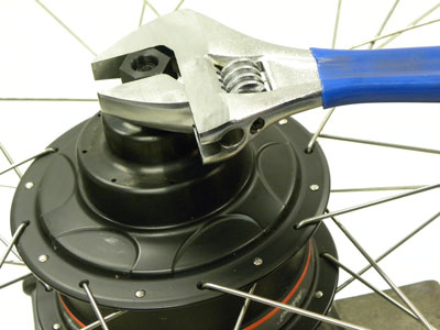
Figure 54. Pin tool socket available from NuVinci™
Another braking option is the roller brake fitting. It will mate to the hub shell splines and is held in place with the same lockring as the rotor mount fitting (figure 55).
2Shift Lever and Shift Cable Installation and Removal
3Cable Attachment to Hub-Interface
4Installation and Alignment of Hub-Interface
5Installing Rear Wheel
6Shift Cable Attachment to Hub-Interface
7Removing Rear Wheel
8Rear Cog and Freehub Service
9N360 Hub Braking System Interface